|
| |
TRUCK SERVICE MANUAL
TM 5-4210-230-14&P-1
WHEELS, RIMS, TIRES
With the improvement in design of both wheel bolt
holes and mounting bolts or nuts the left-hand threaded parts
are no longer used and right-hand threaded parts are used at
all wheels. To prevent loosening of wheel bolts or nuts, cup-
shaped depressions are formed in wheel disc at the bolt holes
so that when mating cup-shaped nut or bolt is tightened,
elastic pressure against the nut or bolt together with thread
friction prevents loosening in service. For this reason wheel
mounting bolts, nuts and wheel bolt hole surface must not be
lubricated.
It is good practice to tighten wheel nuts daily during the
first 500 miles of service on new vehicles and anytime wheels
have been removed. Regular inspection periods should be
established to' assure keeping nuts tightened.
ONE PIECE DROP CENTER HEAVY DUTY TUBELESS
TIRES (7.00-20 and Up)
The mounting or demounting of heavy duty tubeless
truck tires is accomplished in much the same manner as light
duty or passenger-car type tubeless tires. Consequently,
same precautions for protecting the sealing edges of the tire
beads and rims should be observed. Rims used are all of the
one-piece drop-center type whether they are integral with
wheel (disc type) or demountable (cast type). Because
heavier tires are less flexible, it is suggested that the special
tubeless truck tire tools, which are available, be obtained.
Fig. 30
Fig. 30
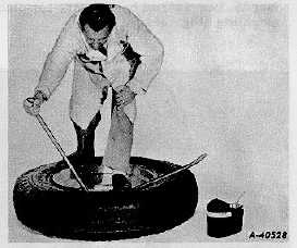
Dismounting Instructions
1.
Remove the valve core to completely deflate tire. With
tire lying flat on the floor, loosen beads from rim seats
by walking around
on tire with heels at points close to rim. With wide side of rim
down, lubricate top bead thoroughly. Insert spoon ends of
both tire irons between rim and tire bead at points about 10"
apart. While standing on tire, pull end of tire iron to the
opposite side of rim so as to pry tire bead up and out of rim
(Fig. 30).
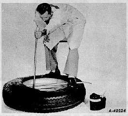
2.
Hold tool in position with one foot and pull second tool
toward center of rim (Fig. 31). Progressively work
bead off rim in this manner, taking additional bites as
necessary.
Fig. 31
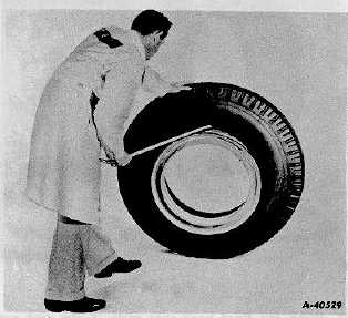
3.
Stand assembly in a vertical position and lubricate
second bead. At top of assembly, insert straight end of
tool between bead and back flange of rim at about 45
degree angle (Fig. 32).
Fig. 32
CTS-2032N Page 11
PRINTED IN UNITED STATES OF AMERICA
|