|
| |
TRUCK SERVICE MANUAL
TM 5-4210-230-14&P-1
WHEELS, RIMS, TIRES
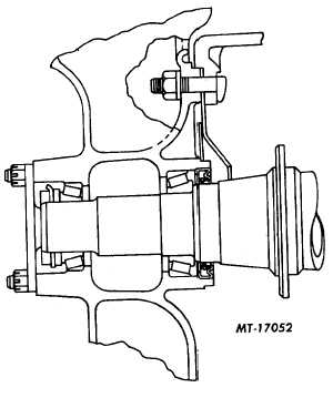
Fig. 4. Medium Duty
REAR WHEEL BEARINGS
Full Floating axle wheel bearings (Fig. 3 and Fig. 4)
are adjusted by an adjusting (inner) nut on end of axle. Install
adjusting nut and rotate wheel while tightening to be sure
bearings are properly seated.
NOTE: 68.0 N•m (50 ft lbs) torque on
adjusting nut is considered sufficient to seat
bearings.
Back off adjusting nut 1/4 turn and install lockwasher
and jam nut. Tighten jam nut to 203 N•m (150 ft lbs) torque
and bend over lockwasher tang to secure nut. Assemblies
which use doweled adjusting nut and pierced wheel bearing
nut lock require 271-407 N•m (200-300 ft lbs) torque on outer
lock nut.
OIL SEALS (OIL LUBRICATED WHEEL BEARINGS)
Various precautions are necessary when oil seals are
installed in wheels and also when wheels with oil seals are
installed on axles. To insure satisfactory performance from oil
seals, the following information has been prepared to guide
and assist in proper installation.
Due to the various types of front and rear axle hub seal
installations, check axle ring and hub seal position at time of
disassembly to assure proper reassembly of new seal and
axle ring (wiper).
OIL SEALS WITH AXLE RING (WIPER)
Axle Ring (Wiper) Installation
1.
Thoroughly clean all parts: axle tube or spindle,
bearings, nuts and inside of wheel hub.
2.
Remove burrs from axle tube or spindle shoulder.
Shoulder must be smooth.
3.
Apply a thin coat of Permatex No. 2 to inside perimeter
of axle ring.
4.
Place axle ring on axle tube or spindle using an
installing tool (Fig. 5).
NOTE: A suitable installing tool can be made
locally by obtaining a piece of standard 8.9
cm
(3-1/2")
inside
diameter
tubing
approximately 25.4 cm (10") long.
Weld a used close fitting bearing cone or large washer
to one end and similarly close opposite end with a plate. This
will enable tool to pilot squarely onto axle tube and permit
driving force to be centered over the complete ring. The same
type of tool can be used for both front and rear axles.
The care with which the axle ring is installed cannot be
over-emphasized. Damage to this ring will result in shortened
seal life.
5.
Tap on end of axle tool driving axle ring firmly on
shoulder until axle tool contacts shoulder. Remove
excess Permatex.
6.
Check position of axle ring to make sure edge of ring is
parallel with shoulder.
CTS-2032N Page 3
PRINTED IN UNITED STATES OF AMERICA
|