|
| |
TRUCK SERVICE MANUAL
TM 5-4210-230-14&P-1
TRANSMISSION
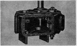
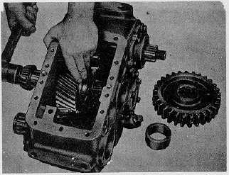
Fig. 29
13. Install spacer and speedometer drive gear over shaft.
14. Position new gasket, bearing cap (and oil seal) over
shaft. Install lockwashers and capscrews and tighten to
specified torque.
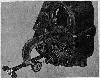
15. Rotate shaft to seat bearings. Mount a dial indicator
against rear .,,d of shaft to check amount of end play in
assembly (Fig. 30). Remove sufficient shims from under
front bearing cap to arrive at an adjustment of zero end
play and zero preload.
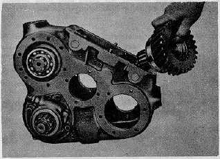
IMPORTANT
The front output gear must be installed in
case before idler assembly is installed.
16. Install ball bearing on hub of gear. Position gear and
bearing in case and install snap ring on bearing (Fig. 31).
Fig. 30.
Fig. 31.
17. Install rear bearing cap over a new gasket. Insert
capscrews and lockwashers and tighten to specified
torque.
18. Press rear bearing on idler shaft. Install snap ring.
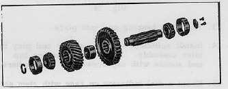
19. Hold Hi gear in position inside case and tap idler shaft
through it with soft hammer. The short hub side of gear
goes to the outside, rear (Fig. 33).
Fig.
32
Fig.
33
CTS-2048Q Page 11
PRINTED IN UNITED STATES OF AMERICA
|