|
| |
TRUCK SERVICE MANUAL
TM 5-4210-230-14&P-1
TRANSMISSION
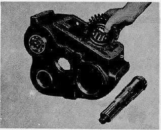
Assembly of Transfer Case
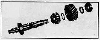
1.
Install front bearing on input shaft with shielded side
against shoulder (Fig. 24).
Fig. 24.
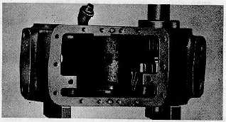
2.
Start input shaft into case. Mount sliding gear, spacer
and drive gear (with bushing) on shaft (Fig. 25).
Fig. 25.
3.
Tap input shaft into position using a suitable sleeve
against the inner race of front bearing.
4.
Position original shim pack plus .254 mm (.010") more to
make sure there is end play in assembly. Install front
cover and tighten capscrews.
5.
Place thrust washer on shaft and install rear bearing with
shielded side toward the inside.
6.
Position a new gasket and attach power-takeoff (or cover,
if used) to rear of case. Tighten capscrews.
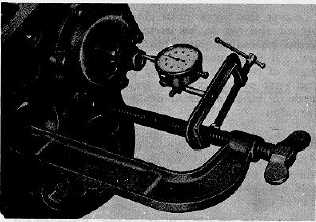
7.
Mount a dial indicator on the unit. Set stem against front
end of input shaft and check the amount of end play in
the assembly (Fig. 26). Remove enough shims from
under bearing cap to arrive at an adjustment of .076 mm
- .127 mm (.003" - .005") end play.
8.
Reposition bearing cap, insert capscrews and tighten to
specified torque. Remove power take-off for convenience
in handling transfer case.
9.
Press front bearing onto rear output shaft with suitable
sleeve.
Fig. 26.
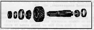
Fig. 27.
10. Hold rear output gear in position inside case and slide
shaft through it (Fig. 28).
11. Install front bearing cup and original shim pack plus .254
mm (.010"). Install bearing cover, lockwasher and tighten
capscrews.
12. Press rear bearing on shaft with a suitable sleeve (Fig.
29); then tap bearing cup into position.
Fig. 28.
CTS-2048Q Page 10
PRINTED IN UNITED STATES OF AMERICA
|