|
| |
TRUCK SERVICE MANUAL
TM 5-4210-230-14&P-1
TRANSMISSION
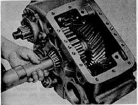
20. Install gear spacer on shaft and then install Lo gear with
long hub toward outside (front) of case.
21. With shaft in 'position, install rear bearing cup in case.
Use a new gasket and install rear bearing cap,
lockwashers and capscrews Tighten capscrews to
specified torque.
22. Drive front bearing onto idler shaft. Hold shaft rigid to
avoid damaging rear bearing and cup (Fig. 34). Install
bearing retainer plate and capscrews. Lock wire.
Fig. 34.
23. Tap front bearing cup into place.
24. Install sufficient shims to set up end play in idler
assembly. Install front bearing cap and secure with
capscrews and lockwashers.
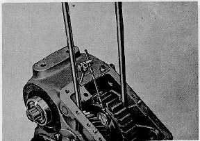
25. Mount a dial indicator on case with stem set against
inside face of Lo gear. Check the amount of end play by
working assembly back and forth with two prybars as
shown (Fig. 35). Remove sufficient shims to arrive at a
bearing adjustment of .076 mm .127 mm (.003" - .005")
end play.
Fig. 35.
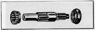
Fig. 36.
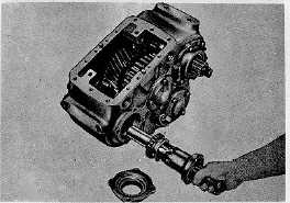
26. Install ball bearing on front output shaft with bearing snap
ring toward outside.
27. Install sliding collar on shaft. Slide shaft into case (Fig.
37).
28. With shaft in position, install a new gasket, bearing cap
and oil seal, lockwashers and capscrews. Tighten
capscrews to specified torque.
29. Position a new gasket and then mount backing plate,
deflector and stamped washer. Insert capscrews and star
washers and tighten to specified torque (Fig. 38).
30. Position brake lever on backing plate.
31. Position brake shoes on backing plate with actuating pawl
in web slot (Fig. 39).
32. Hook up brake shoe return springs.
33. Slide brake hub over splines of front output gear. Install
retaining ring (Fig. 40).
Fig. 37.
CTS-2048Q Page 12
PRINTED IN UNITED STATES OF AMERICA
|