|
| |
TM5-4210-229-14&P
6-15
TRANSMISSION REPAIR (Continued)
(9)
Clutch spline alignment.
Align the internal splines of the third clutch plates to
the external splines on the fourth clutch housing.
Grasp the fourth clutch assembly by the spring
retainer and install it onto the center support hub.
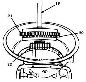
(10) Forward clutch and turbine shaft.
(a)
Align the internal-splined plates of the
fourth clutch, and direct air into the fourth
clutch apply port. The air will apply the
fourth clutch and prevent movement of
the clutch during installation of the
forward clutch assembly.
(b)
Be sure thrust bearing race assembly is in
place, black oxide race (lube scallops)
facing down on the fourth clutch housing
hub (22).
(c)
Install the forward clutch assembly (20)
while engaging the fourth clutch hub (22)
within the internal-splined plates of the
fourth clutch. When the forward clutch
assembly (20) is properly seated, the
front surface of the forward clutch
housing will be approximately 1/2 inch
(12.7 mm) behind the forward edge of the
PTO opening. Another check is to apply
air in short bursts to the fourth clutch and
watch the forward clutch assembly for an
up and down movement. If the assembly
does not move, it is properly seated.
b.
Oil pump and front support installation.
(1)
Install the front support gasket. Be sure the two
hook type sealrings at the base of the turbine
shaft are held in place with oil-soluble grease
(Appendix D, Item 21).
Improper installation of butt-joint sealrings may
cause transmission failure.
(2)
Install thrust bearing race assembly onto the
hub of support assembly black oxide
race (lube scallops) up. Install two butt-joint
sealrings onto the hub. Retain the bearing and
sealrings with oil-soluble grease (Appendix D,
Item 21).
(3)
Lubricate
sealring
with
oil-soluble
grease
(Appendix D, Item 21) and install it onto
support assembly. Install two 3/8-16x6inch
headless guide screws into the transmission
housing. Attach front support lifter to the
converter ground sleeve. Align all the holes in
the front support with the corresponding holes in
the transmission housing. Index two of these
holes in the corresponding holes containing the
two guide bolts and install the front support.
6-89
|

