|
| |
TM5-4210-229-14&P
6-15
TRANSMISSION REPAIR (Continued)
(4) Install ten of the twelve 3/8-16x3-3/8 inch
bolts and rubber-covered washers. Remove
the two guide bolts and install the two
remaining support bolts. Do not tighten the
bolts in sequence. Maintain an even pull on
the outer perimeter of the support by
tightening the first two bolts 180 degrees
apart
to
15
ft-lb
(20
N.m).
Move
approximately90 degrees around the bolt
circle and re-peat the operation. Torque the
remaining opposite pairs of bolts. Repeat the
entire process, tightening all twelve bolts
to24-32 ft-lb (33-43 N.m).
c.
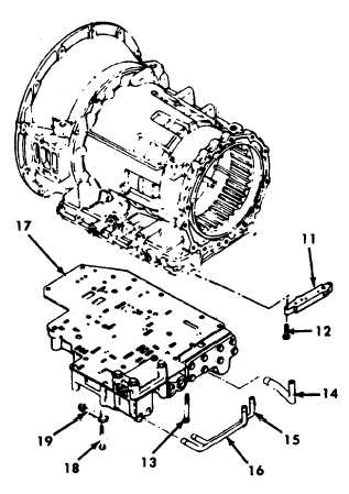
Control valve installation.
With the range selector valve suitably
secured, position the control valve assembly
so the actuator pin enters the housing bore.
Install the control valve body (17) and retain it
with two 1/4-20x3 inch bolts and seventeen
1/4-20x2-1/4 inch bolts. Do not install the two
first clutch feed tube retainer bolts (1 3).
Leave the bolts sufficiently loose to move the
valve body for engagement of the selector
valve with the shift pin.
d.
Tube adapter installation.
(1) Place the tube adapter (11) and tubes
(14)and (15) in position so the tubes can be
inserted into their respective bores in the
valve body.
(2) Install the long first clutch feed tube (14)into
the drilled boss on the valve body. Insert the
governor feed and pressure tubes(15). Be
sure each tube is seated properly.
(3) Install four 1/4-20x1-1/4 inch bolts (12) to
retain the tube adapter (11). Torque the bolts
to 8-12 ft-lb (11-16 N.m)
(4)
Engage the notch in the range selector valve
with the pin on the detent lever. Position the
detent spring (1 9) to engage a notch in the
detent lever and install one 1/4-20x1 -3/4
inch bolt (18) to retain it. Install the two bolts
(13) that retain the first clutch feed tube (14).
Torque the bolt to 8-12 ft-lb (11-16 N.m).
Working from the center outward, torque two
1/4-20x3 inch bolts and seven-teen
1/4-20x2-1/4 inch bolts to 8-12 ft-lb (11-16
N.m).
(1)
e. Valve body installation.
Install
the
modulated
lockup
valve
body
assembly (10). Install three 1/4-20x2 inch bolts
to retain the valve body. Torque the bolts to
8-12ft-lb (11-16 N.m).
f.
Oil filter and pan installation.
When installing the oil filter (7), oil filter tube(8), and
sealring (9), care must be exercised to prevent
twisting the tube or filter in any way that might pinch,
cut or deform the sealring. An air-tight seal must be
maintained to enable the oil pump to draw oil from
the sump free of entrained air.
6-90
|