|
| |
TM5-4210-229-14&P
6.15
TRANSMISSION REPAIR (Continued)
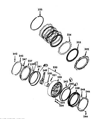
(b)
Beginning with an internal-splined clutch plate,
alternately install three internal-splined (333)
and three external-tanged (334) clutch plates
into the transmission housing. Retain the plates
with snapring (335).
(c)
Remove third clutch piston (237) from center
support assembly (233). Attach center support
lifter into the recess between the sealring
grooves on the sup-port hub.
(d)
Align the tapped hole in the support(233) with
the anchor bolt hole in the transmission
housing. Carefully lower the support into the
housing, seating it firmly against the second
clutch retain-ing snapring. Remove the lifting
bracket from the support. Retain the support by
installing the original 3/8-16x2-1/4 inch self
locking anchor bolt and washer. Tighten the
bolt finger tight.
(e)
Install compressor base over the hub of the
center support (233). Install compressor bar
and center bolt (tool), retaining the bar to the
transmission with two 3/9-16xl-1/4 inch bolts.
Compress the support by applying a torque of 5
ft-lb to center bolt (tool).
(f)
Using center support snapring gauge, measure the
clearance between the top edge of the center support and
the top of the snapring groove in the housing. Select the
proper snapring, using the following table.
Measured
Snapring
Clearance
Thickness
Snapring
in. (mm)
in. (mm)
Color
0.150-0.154
0.148-0.150
White
(3.81)-(3.91)
(3.76)-(3.81)
0.154-0.157
0.152-0.154
Yellow
(3.91)-(3.99)
(3.86)-(3.91)
0.157-0.160
0.155-0.157
Green
(3.99)-(4.06)
(3.94)-(3.99)
0.160-0.164
0.158-0.160
Red
(4.06)-(4.17)
(4.01)-(4.06)
6-84
|

