|
| |
TM5-4210-229-14&P
6.15
TRANSMISSION REPAIR (Continued)
NOTE
All replacement parts orders require information from
the nameplate. Therefore it is imperative that the new
nameplate (331 ) (if replaced)be stamped with
identical information.
(h) Remove the drive screw (330) and nameplate
(331) only if its replacement is necessary.
(2) Assembly.
(a) If the 1/8 inch plugs (328) and (329)were
removed, replace them. Torque the plugs to 4-8
ft-lb (5-11 N.m). If anew nameplate (331) is
required, all information on the old plate must be
metal stamped into the new plate. In-stall the
new plate (331) and retain it with a drive screw
(330).
(b) If lubrication valve (323), spring (324)and tube
(325) were removed, install new parts. Assemble
valve (323) and spring (324) onto tube (325),
respectively. Install the assembly (327) into its
bore in housing (326). Press the valve tube (325)
into its bore until it is 0.58 inch (14.7 mm) below
the external surface of the adapter mounting
boss. Utilization of lube valve spring guide tool
simplifies the installation of the lube valve
assembly (327). Install a new gasket (322) onto
the valve adapter (321). Install the adapter into
the bore. Retain the adapter (321) with two new
1/4-20x7/8 inch socket-head bolts (320). Use
bolts (320) only one time. Torque the bolts to
12-15 ft-lb (16-20N.m).
(c) If plug (317) and washer (318) or the two 1/8 inch
plugs (319) were removed, replace them. Torque
the 3/4-16 plug (317) to 50-60 ft-lb (68-81 N.m).
Torque the two 1/8 inch plugs (319) to4-8 ft-lb
(5-11 N.m).
(d) Place the selector shaft oil seal (311)
sealing lip away from tool onto selector
shaft seal installer. Install the seal(311) into
the housing bore. Lubricate the inner bore of
the seal. Selector shaft seal installer permits
installation of the oil seal with or without the
selector shaft (315) installed.
(e) Guide the grooved end of selector shaft
(315) through seal (311) after removing
burrs from the shaft to protect the oil seal.
Position detent lever (312) so that the
selector valve pin extends toward the inside
of the housing, and engage the slot in the
detent lever with flats on the selector shaft.
Install nut (314) and retainer pin (313) to
retain the shaft and lever. Torque the nut
(314) to 15-20 ft-lb (20-27 N.m)
(f) If the breather (316) was removed, in-stall a
new
breather.
Tighten
the
breather
sufficiently, using care not to distort or crush
the breather stem.
ASSEMBLY
a.
Clutches, center support, planetary gearing and
rear cover assembly.
(1)
Selecting center support snapring.
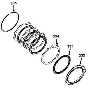
(a) Position the transmission housing, converter
end up. Install second clutch backplace
(332).
6-83
|