 |
|||
|
|
|||
|
Page Title:
POWER STEERING GEAR REPLACEMENT |
|
||
| ||||||||||
|
|
 TM 5-4210-224-14 & P
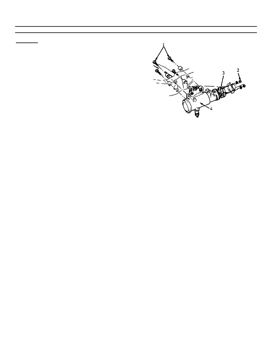
4-227. POWER STEERING GEAR REPLACEMENT (Continued).
REMOVAL
NOTE
Place a drain pan
below
the
steering gear.
a. Remove the hoses from the steering gear.
Raise the hose up to prevent oil drainage. Cap
or tape the ends of the hose and gear fittings to
prevent the entrance of dirt.
b. Remove the lower universal joint pinch bolt.
c. Remove the flexible coupling to steering shaft
flange bolts (2).
d. Remove the pitman arm assembly from the
pitman shaft on the steering gear (paragraph 4-
221).
e. Remove the steering gear frame bolts (1) and
the steering gear (4).
d. Install the pinch bolt into the split clamp.
f. Using a soft mallet, tap lightly on the flexible
e. Torque the pinch bolt to 31 ft-lbs (42 N.m).
coupling (3) to remove the coupling from the
f. Place the steering gear (4) into position, guiding
steering gear stub shaft.
the coupling bolts into the proper holes in the
shaft flange.
INSTALLATION
g. Install the steering gear to frame bolts (1).
h. Torque bolts to 75 ft-lbs (102 N.m).
a. Install the flexible coupling (3) onto the steering
i. Install the coupling flange nuts and washers (2).
gear stub shaft.
The coupling alignment pins should be centered
b. Align the flat in the coupling with the flat on the
in the flange slots.
shaft.
j. Torque coupling flange nuts to 20 ft-lbs (27
c. Push the coupling on the stub shaft until the
N.m).
coupling reinforcement bottoms against the end
of the shaft.
NOTE
Maintain a coupling to flange
NOTE
dimension of 0.250 to 0.375 inch
The pinch bolt must pass through
(6.4 to 9.5 mm).
the shaft undercut.
4-319
|
|
Privacy Statement - Press Release - Copyright Information. - Contact Us |