|
| |
TM 5-4210-220-34
3-8.
ENGINE - Continued
3-8.9
Piston, Liner, Rings, Rod and Rod Bearings - Continued
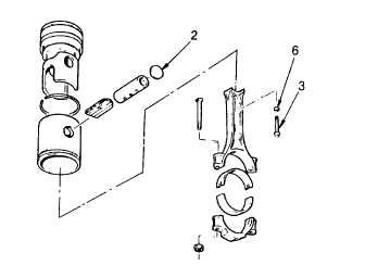
(7)
Install spacers (6) on the two connecting
rod-to-piston pin attaching bolts (3).
(8)
Apply small amount of antiseize compound
(item 4, Appendix B) to bolt threads and
bolt head contact surfaces.
(9)
Aline connecting rod with piston pin and
install bolts (3) fingertight. Clamp rod in
vise and tighten bolts to 60 ft lb (81 Nm).
Do not over torque.
(10) Place piston pin retainer (2) in position.
Place crowned end of installer J23762
against retainer, strike tool hard enough to
deflect retainer and seat it evenly in piston.
Install second retainer.
(11) Inspect the width of the land is even around the retainer.
(12) Place suction cup of detector J23987-01 over retainer and operate the lever to pull vacuum of 10 in. on the
gage. A drop in gage reading indicates leakage at the retainer.
(13) Replace/reseat piston pin retainer if there is any leakage.
(14) With the liner installed in the block, and the block and piston at room temperature, use feeler gage J5438-01
to measure skirt to liner clearance, hold piston upside-down in liner and check clearance in four places 90
deg. apart.
(15) Select a feeler gage with a thickness that will require a pull of six lbs to remove. The clearance will be 0.001
in. (0.03 mm) greater than the thickness of the feeler gage. The clearance must be less than 0.012 in. (0.31
mm).
(16) If any binding occurs between piston and liner, examine piston and liner for burrs. Remove burrs with fine
hone and recheck clearance.
(17) Pistons are fitted with three compression rings and two oil control ring assemblies.
(18) Insert one compression ring at a time into the cylinder liner in the ring travel area. Liner can be in block or
reconditioned on bench. Use a piston skirt to push ring parallel with top of liner’ and measure ring gap with
feeler gage. The end gap should be 0.025 - 0.045 in. (0.64 - 1.14 mm).
(19) If the gap on compression ring is insufficient it may be increased by filing the ends of the ring. File so the
cutting action is from the outer surface to the inner surface to prevent chipping or peeling of chrome plate on
ring.
(20) Check ring side clearance on piston in each compression groove. The top fire ring clearance, measured with
the keystone fire ring flush with the outside diameter of the piston crown should be 0.0010 - 0.0050 in. (0.025
- 0.127 mm).
3-170
|