|
| |
TM 5-4210-220-34
3-8.
ENGINE - Continued
(21) The clearance on rectangular compression ring # 2 should be 0.0100 - 0.013 in. (0.254 - 0.330 mm).
(22) Clearance on rectangular compression ring # 3 should be 0.0040 - 0.0070 in. (0 102 - 0.178 mm).
(23) Repeat procedure for oil control rings. The gap for the rings in the lower groove must be 0.0100 - 0.0250 in.
(0.254 - 0.635 mm) and 0.0070 - 0.0170 in. (0.178 - 0.432 mm) in upper groove. The clearance for both
rings installed in each groove must be 0.0015 - 0.0055 in. (0.038 - 0.140 mm).
NOTE
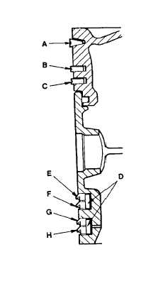
New piston rings must be installed
whenever a piston is removed. The top
fire ring (A) and the second groove ring
(B) are pre-stressed. Both are identified
by an indentation mark on the top side.
The fire ring is chrome plated on the
lower side.
(24) Starting
with
bottom
ring
(C),
install
compression rings with expander J8128.
Do not spread them any more than
necessary to slip them over the piston.
Stagger ring gap 180 deg. from each other.
(25) Place piston on bench, inverted.
(26) Install the ring expanders (D) in the oil
control ring grooves in the piston skirt.
Install with free ends pointing towards
piston crown. Use care not to overlap ends
of expanders which would result in oil ring
breakage.
NOTE
The scraper edges of all oil control rings
must face downward toward bottom of
piston for proper oil control.
(27) Install oil control rings by hand. Start with the upper half (E) of the top oil ring, locate gap 180 deg. from
expander gap (D). Ring has chrome outside diameter and is color coded with orange stripe.
(28) Install lower half (F) of the top oil ring. Locate gap 90 deg. from upper half. Ring is not chromed and is color
coded with orange stripe.
(29) Install the upper half (G) of the bottom oil ring. Locate gap 180 deg. from expander gap.
(30) Install the lower half (H) of the bottom oil ring. Locate gap 90 deg. from upper half both rings slotted on
bottom side and are plain black.
(31) Lubricate piston grooves and rings with engine oil. (item 17, Appendix B).
3-171
|