|
| |
TM 5-4210-220-34
3-8.
ENGINE - Continued
NOTE
Four inserts are available to adjust liner height during installation.
Size
Thickness
Identification
(New Inserts)
std.
.1188 - .1193 in.
Black oxide or 2 purple stripes
std.
.1200 - .1205 in
No Color
std.
.1212 - .1217 in.
Copper or 2 orange stripes
+.015in.
.1362 - .1367 in.
White and orange stripe
(11) Mark liner and block with felt pen so liner may be reinstalled in same position in the same block bore.
(12) Remove cylinder liner hold down clamps.
b.
Piston Installation
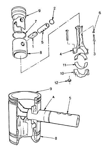
(1) Install bearing bushing (1) into the piston crown. It should slide in without force. It must be installed before
assembling piston skirt (8) to crown (9).
(2) Lubricate the metal seal ring (7) with engine
oil (Item 17, Appendix B) and install into
ring groove of crown with the chamfer
toward the bottom of piston.
(3) Compress
seal
ring
(7)
with
ring
compressor J24226.
(4) Push skirt (8) into position on the piston
crown (9)
(5) Place piston assembly resting crown down
on bench. Rotate skirt full 360 deg. on
crown. Seal ring must not bind or have any
tight spots. If seal ring sticks, remove tight
spots with flat file. Replace piston crown if
binding cannot be relieved.
(6) Lubricate piston pin (5) with engine oil (item
17, Appendix B). Line up the piston pin
opening in the piston skirt (8) with the
bearing opening in piston crown (9) with
alinement tool J24285 (A) to prevent
damage to pin (5) or bearing (1). Then
install piston pin.
3-169
|

