|
| |
TM 5-4210-220-34
3-8.
ENGINE Continued
3-8.3
Blower Continued
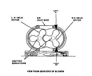
(C)
Rotor to Housing Clearance Air Inlet
Side minimum 0.015 in. (0.381 mm)
(D)
Rotor to Housing Clearance Air Outlet
Side minimum 0.004 in. (0.102 mm)
NOTE
One serration is omitted on the drive end of each blower rotor shaft and a corresponding serration is
omitted in each gear. Assemble the gears on the rotor shafts with the serrations in alinement. The center
punch mark in the end of each rotor shaft at the omitted serration will assist in alining the gears on the
shafts. If shims were removed from the back side of the gears (between the inner race of the bearing and
the gear), they should be replaced in their original positions before installing the gears on their respective
shafts.
(90) Place the blower assembly on the bench, with the top of the housing up and the rear end (serrated end of
rotor shafts) of the blower facing the outside of the bench.
(91) Rotate the rotors to bring the omitted serrations on the shafts in alinement and facing to the left as shown.
(92) Install a 0.140 in. (3.56 mm) thick gear
spacer
and
the
same
number
and
thickness of shims (24) on each rotor shaft
that
were
removed
at
the
time
of
disassembly.
(93) Lubricate the serrations of the rotor shafts
with engine oil (item 17, Appendix B).
(94) Place the teeth of the rotor gears in mesh
so that the omitted serrations inside the
gears are in alinement and facing the same
direction as the serrations on the shafts.
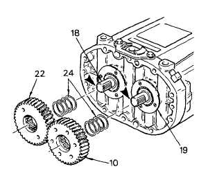
(95) Start both rotor gears straight on the rotor shafts with the right-hand helix gear (10) on the right-hand helix
rotor (19) and the left-hand helix gear (22) on the left-hand helix rotor (18), with the omitted serrations in the
gears in line with the omitted serrations on the rotor shafts.
(96) Thread a 1/2 in. 20 x 1-1/4 in. bolt with a thick washer into the end of each rotor shaft. Place a clean folded
cloth between the lobes of the rotors (18 and 19) to prevent the gears from turning. Draw the gears into
3-122
|