|
| |
TM 5-4210-220-34
3-8.
ENGINE Continued
(80) Install the second ball bearing on the remaining rotor shaft in the same manner.
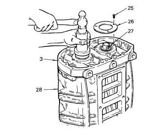
(81) Place the bearing retainers (26) on top of the bearings (23) and the end plate (7). Then install the self-locking
screws (25). Tighten the screws to 9 ft lb (12 Nm).
NOTE
To install the roller bearing inner races
on the rotor shafts at the front end plate,
carry out steps 82 thru 84 following.
(82) Reverse the position of the blower housing
on the two wood blocks.
(83) Position the roller bearing inner race over
the front end of the rotor shaft and press
the race on the shaft with tool J6270-13
until the bearing contacts the shoulder on
the shaft. Similar to steps 79 and 80
preceding.
(84) Install the bearing inner race on the front
end of the other rotor in the same manner.
NOTE
To install the roller bearing outer race assemblies in the front end plate (3), carry out steps 85 thru 88
following.
(85) Lubricate one of the roller bearings (38) with engine oil (item 17, Appendix B). Start the bearing (shoulder
side up) over the rotor shaft and bearing inner race and into the end plate (3).
(86) Place installer J6270-13 on top of the bearing and tap the bearing straight on the inner race and into the front
end plate (3). Similar to steps 79 and 80 preceding.
(87) Install the second roller bearing on the remaining rotor shaft in the same manner.
(88) Place the bearing retainers (26) on top of the bearings and the end plate (3). Then install three self-locking
retainer screws (25) in each retainer. Tighten the screws to 9 ft lb (12 Nm).
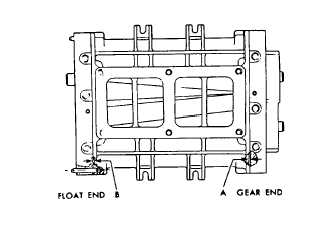
(89) Make a preliminary check of the rotor-to-
end plate and rotor-to-housing clearances
with a feeler gage. Blower clearances are
listed below:
(A)
Rotor to End Plate Clearance Gear
End minimal 0.007 in. (0.178 mm)
(B)
Rotor to End Plate Clearance Float
End minimum 0.012 in. (0.305 mm)
3-121
|