|
| |
TM 5-4210-220-34
3-8.
ENGINE Continued
(97) Remove the two bolts and washers that were used to draw the gears into position on the rotor shafts.
(98) Lubricate the threads of the 1/2 in. 20 x 1-1/2 in. gear retaining capscrews (20) with engine oil (item 17,
Appendix B). Place a spacer (21) on each of the capscrews and thread them Into the rotor shafts. Tighten the
bolts to 110 ft lb (150 Nm). Remove the cloth from the blower rotors.
NOTE
After the blower rotors and timing gears are installed, the blower rotors must be timed. Carry out steps 99
thru 107 to time the blower rotors.
Before timing the blower, install four 5/16 in. 18 x 1-7/8 in. bolts with flatwashers through four bolt holes in
each end plate (top and bottom) and thread them into the blower housing. Tighten the bolts to 17 ft lb (23
Nm). This will hold the end plates against the blower housing so the proper clearance between the rotors
and the end plate can be obtained.
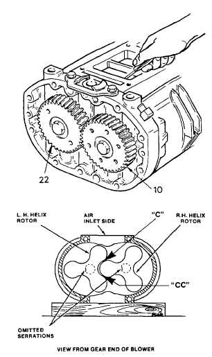
(99)
The blower rotors, when properly positioned
in the housing, run with a slight clearance
between the lobes. This clearance may be
varied by moving one of the helical gears in
or out on the shaft relative to the other gear.
(100) If the right-hand helix gear (10 is moved
out, the right-hand helix rotor will turn
counterclockwise when viewed from the
gear end. If the left-hand helix gear (22) is
moved out, the left-hand helix rotor will turn
clockwise when viewed from the gear end.
This positioning of the gears, to obtain the
proper clearance between the rotor lobes,
is known as blower timing.
(101) Moving the gears OUT or IN on the rotor
shafts
is
accomplished
by
adding
or
removing shims (24) between the gears
and the bearings.
(102) The clearance between the rotor lobes may
be checked with 1/2 in. (12.7 mm) wide
feeler
gages
as
shown.
A
specially
designed feeler gage set J1698-02 for the
blower clearance operation is available.
Clearances should be measured from both
the inlet and outlet sides of the blower.
3-123
|