|
| |
TM 5-4210-220-34
3-8.
ENGINE Continued
3-8.3
Blower Continued
NOTE
When installed, the inside flats of the
sleeve will be parallel to the center line
of the housing.
(72) Lubricate the oil seal rings in the carriers on
the rotor shaft with engine oil (Item 17,
Appendix B).
(73) Position each oil seal rings in Its carrier so
the ring protrudes from its groove the same
amount on each side.
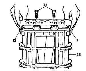
(74) Position the rear end plate (7) over the top
of the rotor shafts with the inner face of the
end plate facing the rotors and the TOP
side of the end plate facing the top side of
the blower housing.
(75) Lower the end plate (7) straight over the rotor shafts until the dowel pins (13) in the end plate contact the
blower housing (28). Then, carefully work the dowel pins into the dowel pin holes in the housing and the oil
seal rings into the collars. Push the end plate tight against the housing (28). If necessary, tap the end plate
lightly with a plastic hammer.
(76) Insert the two fillister head screws (27) through the rear end plate (7) and thread them into the housing (28).
Tighten the screws to 10 ft lb (14 Nm). Do not use lockwashers on these screws.
(77) Check the relationship of the blower end plates to the housing at the cylinder block side of the blower
assembly. The protrusion of the housing with respect to the end plates should not be more than 0.0005 in.
(.013 mm) above to 0.0065 in. (0.165 mm) below the end plate. Excessive protrusion could distort the
housing when the end plate to cylinder block bolts are tightened and cause rotor to housing interference.
NOTE
To install the ball bearings on the rotor shafts and in the end plate, carry out steps 78 thru 81 following.
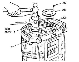
(78) With the blower still supported in a vertical
position on the two wood blocks, lubricate
one of the ball bearings (23) with engine oil
(item 17, Appendix B). Start the bearing,
numbered end up, straight on one of the
rotor shafts.
(79) Place installer J6270-13 on top of the
bearing and tap the bearing straight on the
shaft and into the rear end plate (7).
3-120
|