|
| |
TM 5-4210-220-34
3-8.
ENGINE Continued
(64) With the omitted serration in the splines of the shaft facing toward the top side of the end plate, start the end
of the rotor shaft into the right-hand shaft opening in the end plate so that the gap portion of the seal ring is
started into the ring collar. Continue to lower the rotor and very carefully apply pressure to the seal ring
approximately 180 deg. from the gap while gently working the seal ring into the collar until the rotor contacts
the end plate.
(65) Repeat steps 62 and 63 preceding to prepare the left-hand helix rotor (18).
(66) Position the rotors so the lobes are in mesh and the omitted serrations in the splines of both rotor shafts are
facing toward the top side of the end plate. Then install the left-hand helix rotor as detailed in step 64
preceding.
NOTE
To install the blower housing (28) over
the rotors (18 and 19) and attach to the
front end plate, carry out steps 67 thru
69 following. Make sure to aline the cast
triangle on the blower housing with the
same end plate as marked during
disassembly.
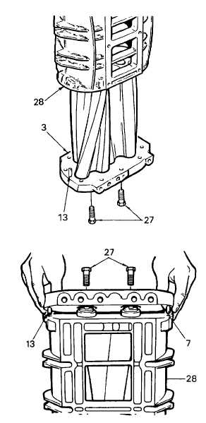
(67) Position the blower housing (28) over the
top of the rotors so the bottom face of the
housing faces the bottom side of the front
end plate (3). Then lower the housing over
the rotors until it contacts the dowel pins in
the end plate (3).
(68) Aline the dowel pin holes in the housing
with the dowel pins (13) in the end plate (3).
Then push the housing (28) tight against
the end plate. If necessary, tap the housing
lightly with a plastic hammer.
(69) Insert the two fillister head screws (27)
through the front end plate (3) and thread
them into the housing (28). Tighten the
screw to 10 ft lb (14 Nm). Do not use
lockwashers on these screws.
NOTE
To install the blower rear end plate on
the rotor shafts and housing, carry out
steps 70 thru 76 following.
(70) Check the dowel pins (13) project 0.320 in.
(8.13 mm) from the flat inner face of the
rear end plate (7) to
assure
proper
alinement of the end plate with the housing
(28).
(71) If removed, press a new bolt guide sleeve
(bushing) into one bolt hole in the bottom
side of the end plate. Install the sleeve, with
the three notches on the sleeve to the
bottom side of the end plate and the center
notch to the outside of the end plate, flush
to 0.005 in. (0.13 mm) below the surface of
the end plate.
3-119
|

