|
| |
TM 5-4210-220-34
3-8.
ENGINE Continued
3-8.3
Blower Continued
(57) Place the oil seal ring collar installer J6270-3 on top of the seal ring collar (35) and under the ram of the
press. Then, press the collar into the end plate (3) until the shoulder on the installer contacts the end plate.
NOTE
A step under the shoulder of the installer will position the collar approximately 0.005 in. (0.127 mm) below
the finished face of the end plate. This is within the 0.002 to 0.008 in. (0.051 to 0.203 mm) specified.
(58) Install the remaining oil seal ring collars (35) in both front and rear end plates in the same manner.
The lobes on the driving blower rotor and the teeth on its gear form a right-hand helix while the lobes and
teeth of the driven rotor and gear form a left-hand helix. Hence, a rotor with right-hand helix lobes must be
used with a gear having right-hand helix teeth and vica versa.
NOTE
To install the blower rotors into the blower front end plate, carry out steps 59 thru 66 following.
(59) Check the dowel pins (13) project 0.320 in. (8.13 mm) from the flat inner face of the front end plate to ensure
proper alinement of the end plate with the housing.
(60) If removed, press a new bolt guide sleeve (bushing) into one bolt hole in the bottom side of the end plate.
Install the sleeve, with the three notches on the sleeve to the bottom side of the end plate and the center
notch to the outside of the end plate, flush to 0.005 in. (0.13 mm) below the surface of the end plate.
NOTE
When installed, the inside flats of the
sleeve will be parallel to the center line
of the housing.
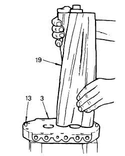
(61) Support the front end plate (3) on two wood
blocks approximately 4 in. (100 mm) high,
with the inner face of the end plate (3)
facing up and the TOP side of the plate
facing to the right.
(62) Lubricate the oil seal ring in the carrier on
the front end of the right-hand helix rotor
shaft with engine oil (item 17, Appendix B).
(63) Hold the right-hand helix rotor (19) in a
vertical position (gear end up) and position
the seal ring in the carrier so the ring
protrudes from its groove the same amount
on each side and the gap is facing away.
3-118
|