|
| |
TM 5-4210-220-34
3-8.
ENGINE - Continued
(7)
Pull the governor and fuel pump assembly from the dowels in the blower end plate.
(8)
Remove capscrews (17) and washers (18), then remove the fuel pump (19), drive coupling fork (21), and the
fuel pump gasket (20). Discard gasket.
NOTE
To disassemble the blower carry out steps 9 thru 18.
Any component is given the same item number on all illustrations following for this procedure including the
exploded view.
(9)
Place a clean folded cloth between the rotors and remove the locking bolts (20) and thick washers (21) that
secure the timing gears (10 and 22) to the blower rotor shafts.
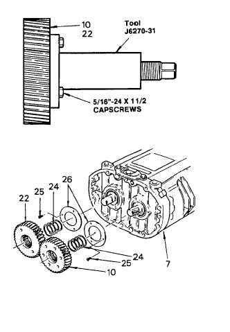
(10) Remove the timing gears with puller tool
J6270-31. Both gears must be pulled at the
same time. Back out the center screws of
both pullers and place the flanges against
the gear faces, alining the flange holes with
the tapped holes in the gears. Secure the
pullers to the gears with 5/16 in. 24 x 1 -1 /2
in. capscrews (two capscrews on the left
helix gear (22) and three capscrews on the
right helix gear (10)).
(11) Turn the two puller screws uniformly
clockwise and withdraw the gears (10 and
22) from the rotor shafts.
(12) Remove the shims (24) from the rotor
shafts, after the gears (10 and 22) have
been removed. Note the number and
thickness of shims on each rotor shaft to
ensure
identical
replacement
when
reassembling the blower.
(13) Remove the self locking screws (25)
securing the rotor shaft bearing retainers
(26) to the rear end plate (7). Remove the
retainers. Repeat this procedure for the
retainers on the front end plate.
(14) To ease assembly procedures, locate the cast triangle on the blower housing and identify the adjacent end
plate similarly. Make sure the identification mark does not mark any sealing surface.
NOTE
To remove the blower rear end plate and ball bearing assembly from the blower housing and rotors, carry
out steps 15 thru 18.
3-111
|