|
| |
TM 5-4210-220-34
3-8.
ENGINE Continued
3-8.3
Blower Continued
(15) Remove the two fillister head screws (27)
securing the rear end plate (7) to the blower
housing (28) and loosen the two fillister
head screws securing the front end plate to
the blower housing approximately three
turns.
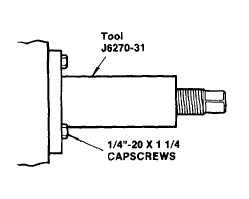
(16) Back out the center screws of pullers
J6270-31 far enough to permit the flange of
each puller to lay flat on the face of the end
plate.
To avoid damaging the blower end plate,
be
sure
that
the
puller
retaining
capscrews are threaded all the way into
the tapped holes in the end plate to
provide maximum anchorage for the
pullers.
(17) Align the holes in each puller with the tapped holes in the end plate and secure the pullers to the end plate
with six 1/4 in. 20 x 1-1/4 in. capscrews.
(18) Turn the two puller screws uniformly clockwise and withdraw the end plate and bearings from the blower
housing and rotors.
NOTE
To remove the blower front end plate and roller bearing assembly from the blower housing and rotors,
carry out steps 19 thru 21.
(19) Remove the fuel pump drive bolt (29), washer (30), drive plate (32) and spacer (31).
(20) Remove the two fillister head screws (27), securing the front end plate (3) to the blower housing (28).
(21) Pull the front end plate and roller bearings from the housing and rotors. The roller bearing inner races will
remain on the shaft of the rotor and the oil seals could be damaged.
(22) Withdraw the blower rotors from the housing.
NOTE
To remove the bearings, oil seals, carriers, roller bearing inner races, and collars from the blower rotor
shafts, carry out steps 23 thru 32.
(23) Clamp one lobe of rotor (19) in a bench vise equipped with soft jaws. Tighten the vise just enough to hold the
rotor stationary.
(24) Remove the oil seal ring (34) from the seal ring carrier (33) on each end of the blower rotor shaft with a pair
of snap ring pliers.
3-112
|