|
| |
TM 5-4210-220-34
3-8.
ENGINE Continued
3-8.3
Blower Continued
(30) Install the stop throttle, fuel shutdown and fire pump governor as detailed in para. 2-19.12.
(31) Attach any other accessories to the engine that were removed.
(32) Close the drains and fill the radiator with antifreeze solution as detailed in LO 5-4210-220-12.
(33) Perform the governor and injector rack control adjustments as detailed in para. 2-19.6 and para. 2-19.13.
(34) Run engine and check for coolant or oil leaks. Repair or tighten connections as necessary.
REPAIR
NOTE
Blower removed from engine (see REMOVAL preceding). If the blower is to be disassembled it is
recommended to replace all seals and bearings. Blower repair kit, (5108123) contains all the necessary
parts.
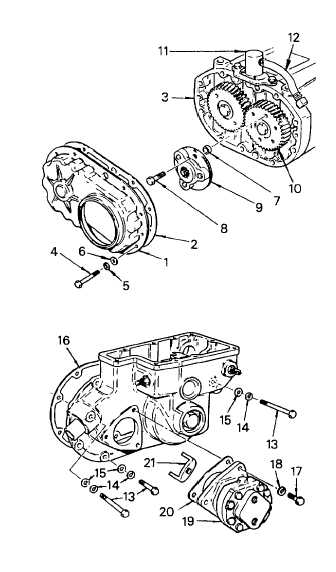
To remove the blower rear end plate
cover, and the governor and fuel pump
assembly, carrying out steps 1 thru 8.
(1)
Remove the capscrews (4), lockwashers
(5), and special washers (6) securing the
rear end plate cover (1) to the blower end
plate (3).
(2)
Remove the cover (1) and gasket (2) from
the blower end plate (3). Discard gasket (2).
(3)
Remove the three locking bolts (8) and
washers securing the drive assembly (9) to
the right-hand blower rotor gear (10).
Remove the drive assembly (9) from the
gear, being careful not to drop the thin hub
spacers (7).
(4)
Remove the mini-bypass blower (11) and
hose (12) from the blower end plate (3).
(5)
Note the location of the two copper
washers, one plain washer and eight
lockwashers on the governor to blower
capscrews before removing them. Remove
the ten capscrews (13) and washers (14
and 15) (two inside and eight outside the
governor housing) securing the governor
and fuel pump assembly to the blower end
plate.
(6)
Tap the sides of the governor and fuel
pump housing lightly with a soft faced
hammer to loosen it from the blower end
plate. Remove and discard gasket (16).
3-110
|