|
| |
TM 5-4210-220-34
3-8.
ENGINE - Continued
3-8.3
Blower
This task covers
a. Removal
b. Installation
c Repair
TOOLS
Air Cleaner Removed (see TM 5-4210-220-12)
Shop Equipment, Automotive
Engine Canopy Removed (see TM 5-4210-220-12)
Maintenance and Repair,
Turbocharger Removed (see TM 5-4210-220-12)
NSN 4910-00-754-0705
Engine Coolant Drained (see LO 5-4210-220-12)
J33001 Alinement Tool
Wheels Blocked
J6270-F Blower Service Tool Set
Air Tanks Drained
J1698-02 Feeler Gage Set
Alternator Removed (see TM 5-4210-220-12)
EQUIPMENT CONDITION
MATERIALS/PARTS
Main Engine Shutdown (see TM 5-4210-220-12)
10, Appendix B Dry Cleaning Solvent
APU Shutdown (see TM 5-4210-220-12)
21, Appendix B Petroleum Jelly
Batteries Disconnected (see TM 5-4210-220-12)
5149641 Installation Kit
Both Engine Compartment Covers Removed (see TM
5149510 Rocker Cover Gasket
5-4210-220-12)
5104507 Alternator Drive Gasket
WARNING
JP-4 is a highly volatile fuel. Extraordinary care must be taken when servicing components that use this
fuel. The truck shall be grounded to an approved grounding point if it contains JP-4.
REMOVAL
NOTE
This task can be completed with the engine mounted in the truck or with the engine removed.
The engine governor components are assembled
in a combination governor housing and blower
front end. cover. The fuel pump is also attached
to the front end of the blower. Therefore, when
removing the blower assembly from the engine,
the governor and fuel pump will also be removed
at the same time.
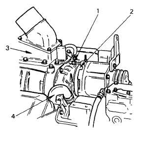
(1)
Loosen the oil pressure line fitting (1) from
the rear of the blower to the blower drive
support and slide the fitting back on the
tube.
(2)
Loosen the hose clamp (2) securing the
blower drive support-to-blower seal.
(3)
Remove the air inlet housing (3) from the
top of the blower. Remove and discard
gasket.
3-104
TM 5-4210-220-34
|