|
| |
TM 5-4210-220-34
3-8.
ENGINE - Continued
3-8.2
Turbocharger - Continued
(42) Aline turbine housing and center housing marks and bring the two housings together. Secure in place
with ’V’ band coupling. Lubricate bolt threads with antiseize compound (item 3, Appendix B). Tighten to
160 In. lb (18 Nm).
(43) Loosen coupling band nut, and retighten again to 160 in. lb (18 Nm).
(44) Aline compressor housing and backplate marks and bring the two housings together. Secure in position
with ’V’ band coupling. Lubricate threads with engine oil (item 17, Appendix B).
Tighten nut to 120 in. lb (18 Nm).
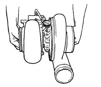
(45) Position dial indicator J8001-3, swivel adapter J7872-3, extension rod J7872-1, and base J7872-2 on
turbine housing base.
(46) Insert extension rod into oil drain hole against wheel shaft. Position so rod is perpendicular to shaft.
(47) Grasp each end of rotating assembly. Applying equal pressure at each end, move the rotating shaft
toward and then away from dial indicator, creating a transverse movement in shaft.
Radial movement should 0.003 0.007 in. (0.08 0.18 mm). Replace necessary parts or complete center
section if tolerances cannot be obtained.
(48) Lubricate the unit internally with clean engine oil (item 17, Appendix B) and install protective covers on all
openings until final installation is performed.
(49) Stamp the letter ’R’ in the lower left-hand corner of name plate to indicate that turbocharger has been
reworked.
3-102
|

