|
| |
3-8.
ENGINE - Continued
(4)
Remove the bolts and lockwashers and carefully withdraw the alternator pulley assembly and drive
coupling as detailed in para. 2-19.2. Remove and discard the gasket.
(5)
Thread blower drive alinement tool J33001 into end of blower drive shaft. Slide the retaining ring up over
the tool and withdraw the blower drive shaft from the blower.
(6)
Loosen clamp and disconnect the breather pipe (4) at the top of the cylinder block. Discard gasket.
(7)
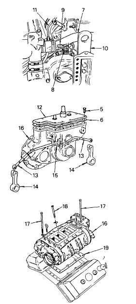
Loosen the hose clamps and slide the hoses
back on the bypass tube (7) between the
thermostat housings. Remove the bypass tube.
(8)
Tag and remove the fuel inlet (8) and outlet (9)
lines to the fuel pump. Remove the fuel return
crossover hose (11) between the cylinder
heads.
(9)
Remove the front engine lifter bracket (10) to
obtain more working space, if necessary. Prior
to removal of bracket, fan and fan clutch have
to be removed as detailed in TM 5-4210-220-
12.
(10) Remove the throttle and fuel shutdown plate
and the fire pump governor as detailed in para.
2-19.12.
(11) Clean and remove the rocker cover from each
cylinder head, see para. 2-19.3.
(12) Remove the governor cover screws (15) and
remove the governor cover (1 2). Discard
gasket (6).
(13) Disconnect the fuel rods (13) from both injector
control tube levers (14) and the governor lever
(15), then remove the fuel rods.
(14) Loosen the hose clamps on the fuel rod cover
tube hoses next to each cylinder head and slide
each hose and clamp up on tube on the
governor housing (16).
(15) Remove the two capscrews (17) and-washers
from the top of each blower end plate.
(16) Remove the blower-to-cylinder block capscrews
(18) and retaining washers on each side of the
blower.
(17) Tag, disconnect, and remove any tubing or
accessories that may interfere with blower
removal.
3-105
|

