|
| |
TM 5-4210-220-34
3-7.
TRANSMISSION-Continued
Gage
Snap Ring
Snag Ring
Lug
Color Code
Thickness
0.149 in.
Blue
0.148-0.150 in.
(3.78 mm)
(3.76-3.81 mm)
0.153 in.
Yellow
0.1.52-0.154 in.
(3.88 mm)
(.86-3.91 mm)
0.156 in.
White
0.155-0.157 in.
(3.96 mm)
(3.94-3.99 mm)
0.159 in.
Red
0.158-0.160 in.
(4.04 mm)
(4.01-4.06 mm)
NOTE
If a red selective snap ring fits loosely, a red snap ring can be used in place of the white snap ring under
the center support to retain second clutch. If the selective snap ring continues to be loose, refer to the
following list for two service released snap rings of thicker dimension, to be used in the selective snap ring
location.
Snap Ring
Snap Ring
Snap Ring
P/N
Color Code
Thickness
23013848
Orange
0.162-0.164 in.
(4.11-4.16 mm)
23013852
Orange/
0.165-0.167 in.
Blue
(4.19-4.16 mm)
(8)
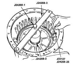
Install the selected snap ring to retain
the center support . Be sure the snap
ring gap is at the top of the transmission
housing.
(9)
Remove
compressor
J24208-3
and
sleeve J24208-2.
(10
The second clutch clearance is checked
by direct measurement of clutch pack.
(11)
Invert the transmission housing, rear
cover upward.
(12)
Remove the six bolts and washers that
temporarily retained the rear cover to the
transmission housing. Remove the rear
cover and gasket.
(13)
Remove the thirteen low clutch plates from the adapter housing. Since these plates are preset for the low
clutch clearance, they should be maintained in a package form so they cannot be intermixed with other
plates.
(14)
Remove the adapter housing and gasket from the transmission housing.
(15)
Remove the thirteen first clutch plates from the transmission housing. These plates were preset for
proper clearance and should be maintained as a package for final installation.
3-71
|