|
| |
TM 5-4210-220-34
3-7.
TRANSMISSION-Continued
(4)
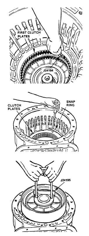
Using gage J24194, check the clearance
between the first clutch plates. It is
recommended
the
gage
be
placed
between the transmission housing and
the first steel plate. The prescribed
clearance is 0.095-0.145 in. (2.41-3.68
mm). Any dimension within 0.095-0.145
in.
(2.41-3.68
mm)
is
satisfactory.
Replace worn clutch plates with new
plates
to
establish
the
desired
clearance. Recheck the clearance.
ah.
Selection of Proper Center Support Snap
Ring
(1)
Install thirteen second clutch plates,
beginning with an external-tanged plate.
Alternately install seven external-tanged
plates and six internal-splined plates.
(2)
Retain the plates with the selective snap
ring. The snap ring should be color
coded white, 0.155-0.157 in. (3.94-3.99
mm).
(3)
The third-clutch piston was left from the
center support assembly during rebuild.
Install bracket J24195 into the recess
between the seal ring on the center
support hub.
(4)
Install
center
support
into
the
transmission housing. Be sure the
tapped hole in the support is alined with
the anchor bolt hole in the bottom of the
housing. Second clutch piston already
Inspected repaired and installed in
center support.
(5)
Remove lifting bracket J24195 from the
center support. Install a 3/8-16 x 3 in.
anchor bolt into the support through the
anchor bolt hole in the bottom of the
housing. Tighten the bolt fingertight.
(6)
Place the compressor sleeve J24208-2
on the hub of the center support. Place
compressor
J24208-3
across
the
transmission
housing.
Retain
the
compressor bar with two bolts.
(7)
Compress
the
center
support
by
applying a torque of 5 ft lb (6.8 Nm) to
the center screw J24208-1. Determine
the width of the snap ring opening, using
gage J33127. Gage lug thicknesses are
stamped on the tool shaft. Select one of
the snap rings in the following list.
Select the thickest snap ring that can be
put into the groove.
3-70
|

