|
| |
TM 5-4210-220-34
3-7.
TRANSMISSION-Continued
(16)
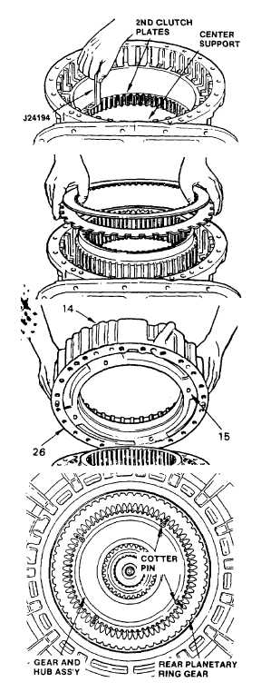
Using gage J24194, check the second
clutch
plate
clearance.
It
is
recommended
the
gage
be
placed
between the transmission housing and
the first steel plate. The prescribed
clearance is 0.095-0.145 in. (2.41-3.68
mm). Any dimension within 0.095-0.145
in.
(2.41-3.68
mm)
is
satisfactory.
Replace worn plates with new plates to
establish
the
desired
clearance.
Recheck the clearance.
NOTE
Leave the second clutch and the center support
in the transmission housing until the housing Is
again positioned front end upward.
(17)
Install, one external-tanged and one
internal-splined plate from premeasured
and properly calculated first clutch pack.
(18)
Install the rear planetary ring gear,
stepped diameter upward.,
(19)
Install the remainder of the first clutch
removed. Begin with an external-tanged
plate, and alternately install six external-
tanged and five internal-splined plates.
The last plate must be a thick external-
tanged plate.
(20)
Place the adapter housing gasket (26)
on the adapter housing (14). Retain the
gasket on the housing with petroleum
jelly (item 21, Appendix B). Be sure all
holes in the gasket are alined with those
in the housing.
(21)
Carefully place the adapter housing
assembly (14), onto the transmission
housing. Since the dowel pins are
different in size, installation Is simplified.
(22)
Install four 1/8 in. cotter pins 1½ In.
maximum length, into the four oil holes
nearest the rear of the rear planetary
ring gear (13).
(23)
Install gear an hub assembly (9) large
end first into the rear planetary ring gear
(13). The hub will stop when it reaches
the four cotter pins.
3-72
|

