|
| |
TM 5-4210-220-34
3-7.
TRANSMISSION-Continued
ae.
Assembly of Complete Transmission After Overhaul
(1)
Coat the inside diameter of detent lever oil seal with petroleum jelly (item 21, Appendix B) and the outside
diameter with seal retainer sealant (item 26, Appendix B). Install the oil seal, lip first, into the
transmission housing. Use installer J26282 to properly locate the seal in the housing. The seal must
clear the chamfer in the housing.
(2)
Hold detent lever so that the selector valve pin extends toward the side of the housing. Slide the manual
shaft through the opening in the housing, oil seal, and slot in the detent lever. Install locknut and retainer
pin. Tighten the locknut to 20 ft lb (27 Nm).
(3)
Install new breather if removed. Torque to 16 ft lb (22 Nm).
(4)
Place transmission housing in a vertical position, rear upward.
NOTE
Two methods of checking clutch plate clearance
have been established. One method is by direct
measurement. The alternate method is by stack
dimension computation. Method one is detailed
following.
af.
First Clutch Installation
(1)
Beginning with an external-tanged clutch
plate
(24),
alternately
install
seven
external-tanged, and six internal-splined
(25) first clutch plates.
(2)
Install two guide bolts (180 deg. apart)
into the transmission housing. Aline and
install the adapter housing assembly
(14) and gasket (29).
ag.
Low Clutch Installation
(1)
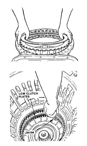
Beginning with an external-tanged clutch
plate, alternately install seven external-
tanged
and
six
internal-splined
low
clutch plates.
(2)
Install
the
rear
cover
assembly,
previously overhauled ready for final
assembly, and gasket onto the rear of
the transmission housing and secure it
with six’ 1/2 - 13 bolts and
lockwashers, evenly spaced. Tighten
the bolts to approximately 30 ft lb (41
Nm).
(3)
Invert the transmission, front upward.
Using gage J24194, check the clearance
between the low clutch plates. It is
recommended
the
gage
be
placed
between the adapter housing wall and
the first steel plate. The prescribed
clearance is 0.095 -0.145 in. (2.41 -3.68
mm). Any dimension within 0.095-0.145
in.
(2.41-3.68
mm)
is
satisfactory.
Replace worn clutch plates with -new
plates
to
establish
the
desired
clearance. Recheck the clearance.
3-69
|

