|
| |
TM 5-4210-220-34
3-7.
TRANSMISSION - Continued
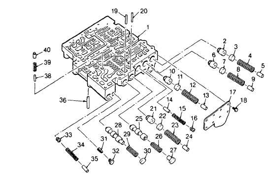
(37) Install trimmer boost accumulator stop (14), spring (15) and trimmer boost accumulator valve (16) into bore of
valve body (1).
(38) Place trimmer valve cover (17) onto valve body (1). Compress the springs and retain the cover with eight 1/4
- 20 X 5/8 in. bolts (18). Tighten the bolts to 8 - 12 ft lb (11 - 16 Nm).
(39) Install priority valve stop (38), spring (39) and priority valve (40) into bore of valve body (1).
(40) Install governor accumulator valve (33), spring (34), and valve stop (35) into bore of valve body (1). Aline stop
(35) and valve body for correct retainer pin installation. Compress spring (34) and install retainer pin (36).
(41) Install governor screen assembly (31), open end first, into bore. Retain the screen assembly with plug (32).
Tighten to 4 - 5 ft lb (5 - 7 Nm).
(42) Install hold regulator (42), spring (43), valve stop (44), washer (46) and adjusting ring (45), flat side first, into
bore of valve body (1).
(43) Aline the pin hole in valve stop (44) with the pin holes in the valve body. Compress the spring, and install
retainer pin (41) into the valve body to retain adjusting ring (45). Be sure the adjusting ring is in the same
position as it was before removal.
(44) Install trimmer regulator valve (70), smaller diameter first, spring (69), and valve stop (68) into bore of valve
body (1). Depress the valve stop and insert retainer pin (72) into its hole in the valve, body.
(45) Install 4-5 relay valve (66), spring (65), and valve stop (64) into bore of valve body. Depress the valve stop
and insert retainer pin (71) into the hole at the front of the valve bore.
3-29
|