|
| |
TM 5-4210-220-34
3-7.
TRANSMISSION - Continued
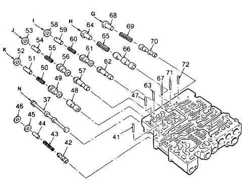
(29) Remove retainer pin (72), spring (69), valve stop (68), and valve (70).
(30) Inspect all valves and springs individually for scoring, breakage or tension fatigue. Inspect main valve body
for scuffed bores. Replace damaged parts.
NOTE
Check the position of all components, the configuration of all valves and plugs, and the identification of all
springs before installation. Place the valve body on a work table, flat side upward. Refer to spring
specification charts (Appendix C). All valves, when dry, should move freely by their own weight, in their
bores.
(31) Install 2-3 relay valve (28), larger diameter first, spring (29) and valve spring spacer (30) into bore. Depress
spacer (30) and install retainer pin (19) into its hole in valve body (1).
(32) Install 3-4 relay valve (25), spring (26) and valve stop (27) into bore. Depress the valve stop and install
retainer pin (20) into its hole in valve body (1).
(33) Install fourth clutch trimmer valve (21) (smaller end first), plug (22). spring (23), and valve stop (24) into bore
of valve body (1).
(34) Install second clutch trimmer valve (10) (smaller end first), plug (11), spring (12), and valve. Stop (13) into
bore of valve body (1).
(35) Install third clutch trimmer valve (2), smaller end first, plug (3), spring (4), and valve stop (5) into bore of valve
body (1).
(36) Install first clutch trimmer valve (6) (smaller end first), plug (7), spring (8), and valve stop (9) into bore of valve
body (1).
3-28
|

