|
| |
TM 5-4210-220-34
2-19.
ENGINE - Continued
2-19.13
Mechanical Governor - Continued
(14)
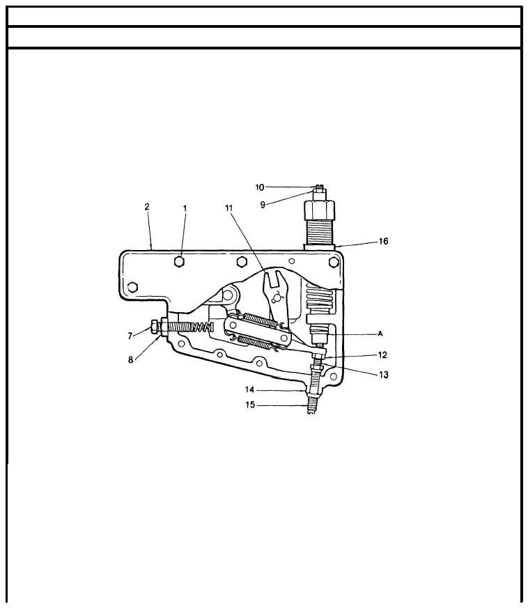
If adjustment is required stop the engine and the back off starting aid screw (15) and locknut (14). Loosen
locknut (12) and adjust gap via screw (13).
(15)
Recheck the gap with the engine operating at 1100 - 1300 rpm. Readjust as required.
(16)
Stop the engine and using a new gasket , install the governor cover with screws . Be sure the pin in the
speed control shaft aligns with the slot in the differential lever (11). Be sure the dowel pins in the housing
aline with the holes in the cover.
(17)
Adjust the position of the injector rack control levers as detailed in para. 2-19.6. Adjust the starting aid screw
as detailed in para. 2-19.6.
(18)
Remove the governor cover and recheck the running gap as detailed in steps 13 thru 16.
(19)
Loosen the spring retainer locknut (16) and back off the high speed spring retainer at 5 turns.
(20)
Start the engine and allow it to reach normal operating temperature.
(21)
With no load on the engine, rotate the speed control shaft fully counterclockwise to the maximum speed
position.
(22)
Turn the high speed spring retainer until the engine is operating at 2250 rpm.
(23)
Holding the high speed spring retainer, tighten the locknut (16).
(24)
With the engine running at normal operating temperature, and the buffer screw (7) backed out, turn the idle
speed adjusting screw (10) until the engine operates at 575 rpm.
(25)
If the engine rolls use the buffer screw to hold the engine at speed. Once 575 rpm is set, back-out the buffer
screw 0.63 in. (17 mrn).
2-250
|

