|
| |
TM 5-4210-220-34
2-19.
ENGINE - Continued
(26)
Holding the idle screw (10) tighten the locknut (9).
(27)
Install the high speed spring retainer cover and tighten the two bolts.
(28)
With the engine running at normal operating temperature, turn the buffer screw (7) in until it just contacts the
differential lever and eliminates engine roll. Do not increase engine idle speed more than 15 rpm.
(29)
Recheck the maximum no-load speed as detailed in step 21.
(30)
If maximum no-load speed has increased more than 25 rpm, back off the buffer screw until speed increase is
less than 25 rpm.
(31)
Hold the buffer screw (7) and tighten the locknut (8).
(32)
Install the engine stop solenoid and foot throttle plate as detailed in para. 2-19.12.
(33)
Replace fan assembly as detailed in TM 5-4210-220-12.
REMOVAL
WARNING
JP-4 is a highly volatile fuel. Extraordinary care must be taken when servicing components that use this fuel.
The truck shall be grounded to an approved grounding point if it contains JP-4.
(1)
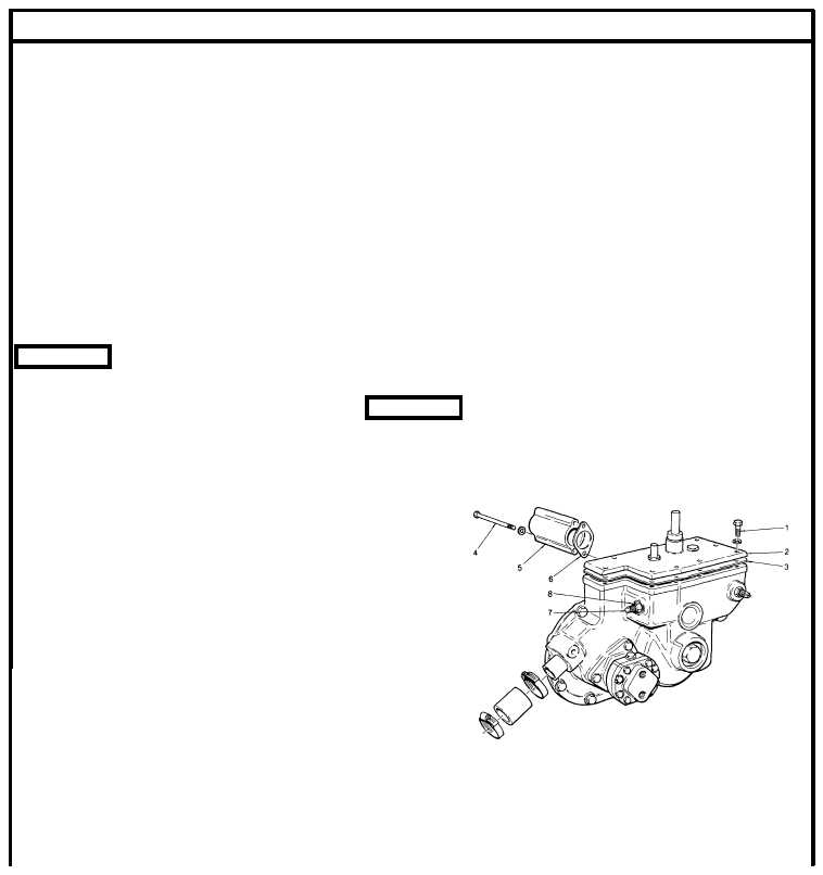
Remove the eight screws (1) and lift off the
governor cover (2). Remove and discard
gasket (3). The stop and speed control
shafts will remain attached to the cover.
(2)
Remove the right bank fuel rod by removing
the screw type pin, in the control link
operating lever, and the clevis pin in the
control tube lever.
(3)
Withdraw the fuel rod from the governor.
(4)
Remove the left bank fuel rod by removing
the clevis pin in the control tube lever and
lift the connecting pin up out of the control
link operating lever 3/4 in. (19 mm).
(5)
Withdraw the left fuel rod from the governor.
(6)
Tag and remove the crossover fuel lines attached to each cylinder head.
(7)
Loosen the hose clamps (4) on the fuel rod cover tube hoses (5). Slide each hose and clamp up the tube on
the governor housing (6).
2-251
|

