|
| |
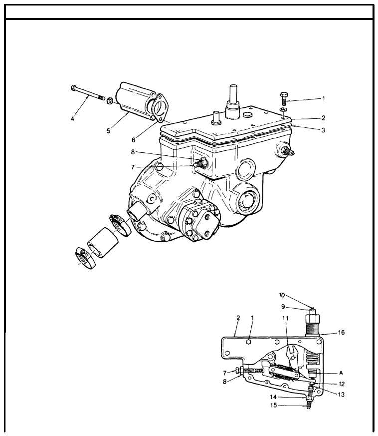
TM 5-4210-220-34
2-19.
ENGINE - Continued
(7)
Remove the engine stop solenoid and foot throttle plate as detailed in para. 2-19.12.
(8)
Remove screws (4) and lift off high speed spring retainer cover (5). Remove and discard gasket (6).
(9)
Back out the buffer screw (7) until it extends approximately 5/8 in. (17 mm) from the locknut (8).
(10)
Start engine and loosen the idle speed
adjusting screw locknut (9). Adjust the idle
screw (10) until the engine is idling at 600
rpm.
(11)
Remove screws (1) and lift off governor
cover (2). Remove and discard gasket (3).
The stop and speed control shafts will
remain attached to the cover.
(12)
Restart the engine and manually operate
the differential lever (11) until the engine is
running between 1100 and 1300 rpm. Do
not overspeed the engine.
(13)
With a feeler gage, check the gap (A)
between the high-speed spring plunger
and the low-speed spring cap. Gap should
be 0.002 0.004 in. (0.05 - 0.10 mm).
2-249
|