|
| |
TM 5-4210-220-34
2-19.
ENGINE - Continued
Be sure all headless plugs are flush to 0.0625 in. (1.6 mm) below the surface of the cylinder head. A 3/8 in. socket head
plLG is installed about 1 in. (25 mm) away from the 2 in. plug on the push rod side. This plug must not protrude more
than 0.0625 in. (1.6 mm) from the block and a 0.2188 in. (5.56 mm) rod placed in the vertical fee hole must pass the
inner face of the plug.
(15) If removed, install the exhaust valves and seats, as detailed in para. 2-19.7.
(16) If removed, install the rocker arms, cam followers, and push rods as detailed in para. 2-19.4.
(17) If removed, replace all cylinder head-to-fuel pipe connector seals. Install all connectors and tighten to 45 ft lb
(61 Nm).
INSTALLATION
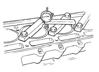
(1) Check the cylinder liner flange heights with respect to the cylinder block using hold down clamp J24565-02 and
depth gage J24898.
(2) The liner flange must be 0.0418 0.0482 in.
(1.0621 1.224 mm) below the surface of the
block. The difference in height between
two adjacent cylinders must not exceed
0.015 in. (0.38 mm). If these limitations
are not satisfied refer to General Support
for repair.
(3) Be sure piston crowns are clean and free of
foreign material.
(4) Be sure each push rod is threaded into its
clevis until the end of the push rod projects
through the clevis.
(5) Be sure all cylinder block and cylinder head
gasket surfaces, counterbores, and seal
grooves are free of foreign material and are
clean.
(6) Be sure there are no burrs or sharp edges in the head or block counterbores.
(7) Inspect the cylinder head bolt holes in the block and remove any water, oil or other foreign material. Check
for any damaged threads.
The 2.00 in. diameter cup plug (thermostat housing end) in a new service head must be removed prior to
installation to prevent blocking the coolant flow out of the head.
(8) Install a new compression gasket on top of each cylinder liner.
(9) Remove the adhesive paper, and place the support shims, adhesive side down in position at each end of the
cylinder block. The scallop in the shim placed at the rear of the block must be at the oil supply hole.
2-217
|