|
| |
TM 5-4210-220-34
2-19.
ENGINE - Continued
2-19.8
Cylinder Head - Continued
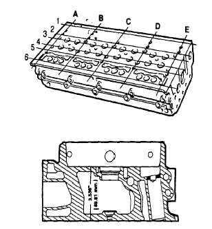
(4) Using a heavy accurate straight edge and feeler
gage J3172, check for longitudinal and transverse
warpage of the head as shown. The maximum
longitudinal warpage allowable is 0.0055 in. (0.140
mm); the maximum transverse warpage allowable is
0.0040 in. (0.102 mm).
To prevent failure of an engine when rebuilt, do not
remove more metal from the fire deck of any cylinder
head below the minimum distance of 3.536 in. (89.81
mm).
(5) The cylinder head may be refaced provided the
injector tubes are removed prior to machining. The
water nozzles may remain in the head.
(6)
After refacing the head, the protrusion of valve seat
inserts (2-19.7), exhaust valves (2-19.7), injector
tubes (2-19.5) injector spray tip spray tips (2-19.5),
and push rods (2-19.4) must be checked and corrected. The water nozzle bores must also be deburred.
(7) Inspect the exhaust valve seat inserts and the valve guides as detailed in 2-19.7.
(8) Inspect the cam follower bores in the cylinder head for scoring or wear. Light score marks may be cleaned
up with emery cloth (item 13, Appendix B).
(9) Measure the diameter of the cam followers with a micrometer and compare with similar readings for each
bore. The follower cylinder head clearance must not exceed 0.006 in. (0.15 mm) with used parts. If the
bores are excessively worn or scored replace the cylinder head.
(10) Check the water hole nozzles for looseness. Replace nozzles if loose as detailed in REPAIR following.
(11) Replace broken or damaged studs. Apply threadlock liquid (item 29, Appendix B) to the new studs. Install
and torque to 40 ft lb (54 Nm).
(12) Inspect the pilot sleeves in the cylinder head bolt holes at each end of the head on the camshaft
side. Replace any damaged or loose sleeves using an arbor press (these sleeves are installed
to provide a close fit for the cylinder head bolts used when installing the head on the engine).
(13) If injectors are removed, remove all cylinder head
to-fuel pipe connectors and inspect for damaged
threads. Remove all seals and discard.
(14) Coat all plugs that were removed cleaning for with
pipe sealant (item Appendix B) and install. Tighten
to the following torques.
NPT Size
Recommended Torque
1/8-27
12 ft lb
(16 Nm)
1/4-18
16 ft lb
(22 Nm)
3/8-18
22 ft lb
(30 Nm)
1/2-14
27 ft lb
(37 Nm)
3/4-14
37 ft lb
(50 Nm)
2-216
|