|
| |
TM 5-4210-220-34
2-19.
ENGINE - Continued
2-19.6
Injector Controls - Continued
REPAIR
NOTE
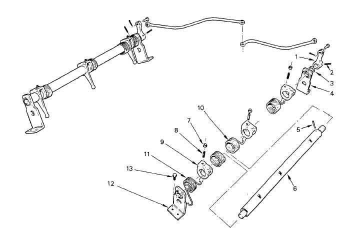
The injector control tube, one mounting bracket, a spacer and an injector control tube lever are available
as a service assembly. When any part of this assembly requires replacing, the complete service
assembly should be replaced. (Items 1 - 6 on the illustration).
Similar procedures apply to both control tube assemblies except as noted. To repair, control tube
assembly must be removed from cylinder head.
(1) On right hand tube, disconnect spring (11) and remove bracket (12) from control tube. On left hand tube,
remove bracket only.
(2) Loosen the adjusting screws (8) and locknuts (7) on each Injector rack control lever.
(3) Disconnect the yield springs (10) from each rack lever and roll the other end of the spring out of the notch on
the control tube.
(4) On left hand tube, disconnect spring (11) from the front bracket.
(5) Slide springs (10 and 11) and rack levers from the control tube.
2-200
|