|
| |
TM 5-4210-220-34
2-19.
ENGINE - Continued
WARNING
Dry cleaning solvent P-D-680 (safety or Stoddard’s solvent) is potentially dangerous. Avoid repeated and
prolonged breathing of vapors and skin contact with the liquid. Do not use near open flame, arcing
equipment or other ignition sources. Always wear eye protection and protective clothing. The flash point
of P-D-680 is 100 to 138 deg. F (30 to 59 deg. C).
Death or serious injury could occur if compressed air is directed against the skin. Do not use compressed
air for cleaning or drying unless the pressure is/has been reduced to 30 psi (2.11 kg/cm2) or less. When
working with compressed air, always use chip guards eye protection and other personal protective
equipment.
(6) Wash all parts in dry cleaning solvent (item 10, Appendix B) and dry with compressed air.
(7) Examine all components for excessive wear cracks or damage and replace as required. Examine bearings in
each bracket as detailed in para. 2-7 and replace bracket and bearing assembly as required.
(8) Examine the yield and return springs and replace if worn or fractured.
(9) For left bank cylinder head carry out steps 10 thru 15 and 21. For right bank cylinder head carry out steps 16
thru 21.
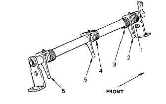
(10) Install the return spring (1) on the control
tube and against the front bracket.
(11) Install a rack control lever (2) with the lever
towards the rear bracket, and the odd (left
hand helix) yield spring (3).
(12) Install the right hand helix yield spring (4)
and rack control levers (5) with the levers
facing the rear bracket.
(13) Attach the curled end of the yield springs to
the rack control lever and roll the yield
springs into the notch or slots.
(14) Turn the adjusting screws and locknuts into the slots only far enough to position the levers on the control
tube.
(15) Attach the curled end of the control tube return spring to the rack control lever and the extended end of the
spring behind the front bracket.
(16) Install the rack control levers (1) with the levers towards the front bracket and the right hand helix yield spring
(2).
(17) Install the left hand helix yield spring (3) and the rack control lever (4) with the lever towards the front bracket.
(18) Attach the curled end of the yield springs to the rack control levers and roll the springs into the notch (left
hand helix spring) and the slots (right hand helix springs) in the control tube.
2-201
|