Order this information in Print

Order this information on CD-ROM

Download in PDF Format


Click here to make tpub.com your Home Page

Page Title: INSTALLATION
Back | Up | Next

Click here for a printable version

Google


Web
www.tpub.com

Home


Information Categories
.... Administration
Advancement
Aerographer
Automotive
Aviation
Combat
Construction
Diving
Draftsman
Engineering
Electronics
Food and Cooking
Math
Medical
Music
Nuclear Fundamentals
Photography
Religion
USMC
   
Products
  Educational CD-ROM's
Printed Manuals
Downloadable Books


TM 5-4210-220-34 2-19. ENGINE - Continued INSTALLATION 
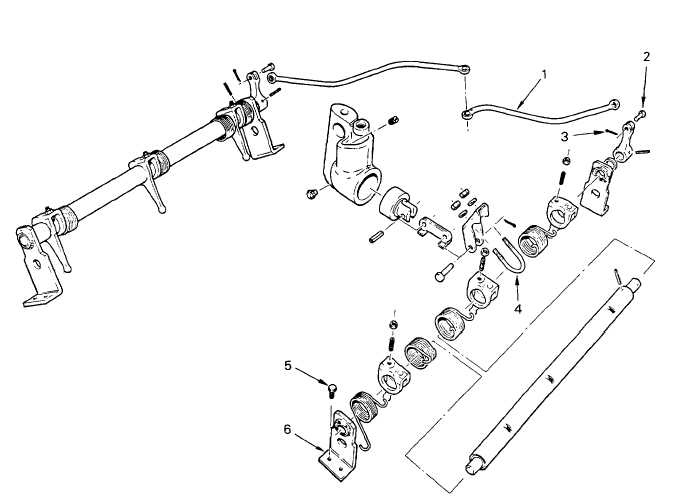
(1)     Engage the injector rack control levers with the injector control racks and aline brackets (6) with the mounting holes on the cylinder head. (2) Install bolts (5) at each bracket (6) and tighten to 12 ft lb (16 Nm). (3)     Check the control tube is free to move In the brackets.  Tap the control tube gently, if necessary,  to aline the bearings in the brackets. (4)     Connect the fuel rods (1) to the injector tube levers with clevis pins (2) and new cotter pin (3). (5) Adjust the fuel rack as detailed in ADJUSTMENT preceding. 2-199

Privacy Statement - Press Release - Copyright Information. - Contact Us - Support Integrated Publishing

Integrated Publishing, Inc. - A (SDVOSB) Service Disabled Veteran Owned Small Business