|
| |
TM 5-4210-220-34
2-19.
ENGINE - Continued
2-19.6
Injector Controls - Continued
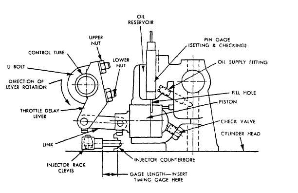
(29) Tighten the U-bolt while exerting a slight pressure on the lever In the direction of rotation.
(30) Remove pin gage and reinsert green end. If it enters with no resistance tighten lower U-bolt nut.
(31) Insert the red end of the gage. If it enters to full depth tighten upper U-bolt nut. This end should not enter
without moving the injector racks toward the no-fuel position.
(32) Remove pin gage and timing gage.
(33) Move the control tube assembly between the no-fuel and full-fuel position to make sure there is no bind.
(34) Adjust governor maximum no-load speed and idle speed as detailed in para 2-19.13.
REMOVAL
(1) Remove U-bolt (4) securing throttle delay actuator to the right-hand injector control tube assembly.
(2) Remove cotter pin (3) and clevis pin (2), securing each fuel rod (1) to the injector control tube.
(3) Remove the bolts (5) from all brackets (6).
(4) Disengage the rack levers from the injector control racks and lift each control tube assembly from the cylinder
head
2-198
|