|
| |
TM 5-4210-220-12
4-26. DRIVE LINES, POWER TRAIN - Continued
(9)
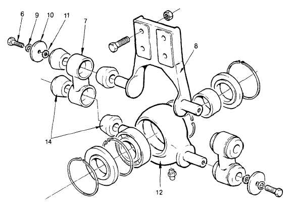
Install one connecting link (7) joining the housing (12) and the bracket (8) together.
(10)
Install the bushings (14) into the connecting link (7).
(11)
Install external tooth washers (11), flatwashers (10), internal tooth washers (9) and capscrews (6).
Fingertighten capscrews (6).
(12)
Install second connecting link (7) similar to steps 10 and 11 preceding.
(13)
Support drive shaft tube in a vise. Tighten the housing capscrews to 70 ft lb (95 Nm).
(14)
Remove the drive shaft tube from the vise and reclamp the vise on the bracket (8). Tighten bracket
capscrews to 70 ft lb (95 Nm).
(15)
Coat the splined area of the shaft back to the bearing shoulder with antiseize compound (item 3,
Appendix E).
(16)
Supporting the drive shaft in a vise, slide the bearing assembly onto the shaft with the machined surface
of the bracket facing away from the splined section of the drive shaft.
NOTE
Shaft and bearing tolerances are close, ensure bearing is square to the shaft during
installation. A soft faced hammer may be used to tap the bearing into position. If bearing will
not slide easily, remove any burrs from shaft or bearing.
4-517
|

