|
| |
TM 5-4210-220-12
4-26 DRIVE LINES, POWER TRAIN - Continued
4-26.5 Center Bearing - Continued
(3)
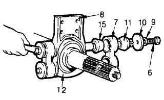
Wipe bushings (14 and 15) with a clean and
dry lint free cloth.
(4)
Check splined shaft journal area, splined
section, and threaded section for damage and
defects. Remove small burrs using emery
cloth (item 13, Appendix E). Use a new
bearing to check shaft. Bearing must slide
onto shaft easily.
(5)
Inspect the housing (12) and bracket (8) for
cracks, oversized mounting holes, damaged
threads or abnormal wear.
(6)
Using a new bearing (16), check bore in housing. If the outer race can spin freely when installed in the
housing, the housing should be replaced. If the bearing is too tight the housing may have burrs or
irregularities. Remove with emery cloth (item 13, Appendix E).
(7)
Inspect connecting links (7) for cracks, or wear.
(8)
Inspect connecting link bushings (14 and 15) for cracking, wearing or deterioration.
(9)
Inspect connecting link fasteners for damaged threads, and inspect washer (9, 10, and 11) for rust or
cracks.
(10)
Inspect bearing covers for rust, dents, or cracks.
(11)
Evidence of damage of any kind is cause for rejection. Replace assembly as required.
INSTALLATION
(1)
If a new bearing assembly is being installed proceed to step 15. If a new bearing is being used, rebuild
bearing prior to installation as detailed following.
(2)
Install one inner snap ring (13) into housing (12).
(3)
Apply grease (item 16, Appendix E) to outer race of bearing.
(4)
Press bearing (16) into the housing (12) until it contacts the snap ring.
(5)
Install the remaining inner snap ring (13) in housing (12).
(6)
Install the bearing covers (17) into the housing and retain with the outer snap ring (13).
(7)
Install the bushings (15) on the bracket (8) and on the housing (12).
(8)
Grasp bracket (8) and support over the housing (12).
4-516
|