|
| |
TM 5-4210-220-12
4-24. ELECTRICAL SYSTEM - Continued
4-24.14 AC Electrical System - Continued
b.
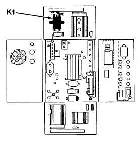
K1 Relay Repair
NOTE
Always check out K2 relay before checking
out K1 relay. This is detailed in a preceding.
(1)
Open the inverter as detailed in a preceding, steps 5
thru 8.
(2)
Locate K1 relay and with battery switch set to BOTH
but Ignition off, connect a voltmeter between the two
small terminals on top of the relay (the coil).
(3)
Without depressing the start button, voltage should be
0 Vdc. With start button depressed, voltage should be
10 Vdc or higher.
(4)
If it is zero with start button depressed recheck K2
relay as detailed in a preceding.
(5)
Check the resistance across the two large terminals at the top of the relay with an ohmmeter
(6)
Without depressing start button, resistance should be greater than 100 kOhms
(7)
With start button depressed, resistance should be less than 5 ohms
(8)
Replace relay K1 if either of these readings is not obtained
(9)
Replace inverter as detailed in steps 13 and 14 of K2 Relay Repair preceding
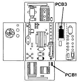
c.
Voltage Regulator PCBI and PCB3 Repair
(1)
Connect the 4-2400 Test Strip to the Dynamic
Inverter plug on front panel of inverter
(2)
Set battery switch to BOTH and the ignition switch
to ON, but the engine not running
(3)
Measure voltage between blue and green on test
strip
(4)
Without depressing the start button, the voltage
should be 10 Vdc or higher. If not, replace the
regulator, PCB3, see 6 following
(5)
With the start button depressed, the voltage
should be 10 Vdc or higher. If not, replace the
regulator PCB1, as detailed following
4-464
|