|
| |
TM 5-4210-220-12
4-24. ELECTRICAL SYSTEM - Continued
(6)
Open the inverter as detailed in a preceding, steps 5 thru 8.
(7)
Unplug PCB1 or PCB3 as required and replace.
(8)
Replace inverter as detailed in steps 13 and 14 of K2 Relay Repair preceding.
d.
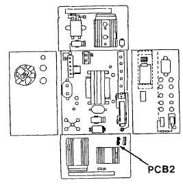
Oscillator Circuit Board PCB2 Repair
(1)
Open the inverter as detailed in a preceding,
steps 5 thru 8.
(2)
Set battery switch to ON, and ignition switch
OFF.
(3)
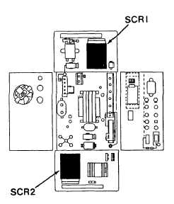
Locate the SCR gate leads, the small white
leads to the SCR's which have a plastic
connector in the lead.
(4)
Tag and separate the leads from the
plastic connector.
(5)
With the start button depressed, read the
voltage
between
the
oscillator
case
(ground) and the part of the gate lead
connected to the oscillator circuit board
PCB2.
(6)
Replace the oscillator board PCB2 if the voltage is not between 2 Vdc and 7 Vdc and the voltage is not
equal on both leads from each SCR ( 0.3 Vdc)
(7)
Replace inverter as detailed in steps 13 and 14 of a preceding
e.
SCR Repair
(1)
Be sure all commutation fuses are not blown.
These four fuses are mounted on the front of the
inverter.
(2)
Open the inverter as detailed in a preceding steps
5 thru 8.
(3)
Leave battery switch OFF.
(4)
Remove SCR cathode (ground) wires from their
ground connection. These are red # 8 wires
which are attached to the bottom of the inverter
with a nut and screw.
(5)
Connect an ohmmeter with positive lead (+) on
heat sink and negative lead (-) on the cathode
removed from ground stud.
4-465
|


