|
| |
TM 5-4210-220-12
4-24. ELECTRICAL SYSTEM - Continued
REPAIR
NOTE
Check out of the inverter requires a 4-2700 test strip to be plugged into
the "Dynamic Inverter" plug on front panel of inverter.
a.
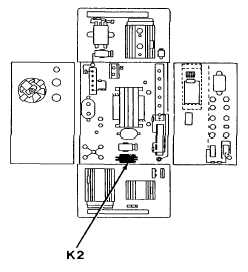
K2 Relay Repair
(1)
Be sure battery switch is set to BOTH, engine not running
(2)
Connect a voltmeter between brown and green on the test
strip
(3)
Press the inverter start button. Voltage should be 10 Vdc or
higher.
(4)
If voltage is less than 10 Vdc replace relay K2, this is
located inside the inverter as shown
(5)
Set battery switch to OFF
(6)
To open inverter, unscrew mounting bolts securing inverter
to bottom of compartment
(7)
Pull inverter forward and remove front, top, and back panel
fasteners
(8)
Carefully lay the front and back panels down and remove the top panel
(9)
Pull relay K2 from its base and replace
(10)
Set battery switch to BOTH and connect voltmeter between blue and green on test strip. With the start
button depressed, voltage should be 10 Vdc or higher. If it is zero, the replaced K2 relay has failed.
Replace.
(11)
If voltage is 10 Vdc or higher, but the voltage between brown and green is still zero, check out the K1
relay as detailed in K1 Relay Repair following.
(12)
If voltage is 10 Vdc between blue and green and between brown and green, K2 relay is satisfactory
(13)
Set battery switch to OFF and replace front, back, and top panels and install fasteners
(14)
Carefully slide unit back into compartment and replace feet retaining bolts
4-463
|

