|
| |
TM 5-4210-220-12
4-24. ELECTRICAL SYSTEM - Continued
(5)
Disconnect battery cables at negative pole of both pairs of batteries.
(6)
Connect a carbon pile across the positive and negative terminals of one battery.
(7)
Reconnect the battery cables, and start the main engine (see Chapter 2). Turn on all accessories.
(8)
Operate engine at 1200 rpm or more and adjust carbon pile as required to obtain maximum current output
from the alternators. Read current on dash-mounted ammeter.
(9)
Check output is greater than 40 amps. If above this figure, the alternators are performing satisfactorily.
(10)
If current is less than 40 amps, loosen belt on one alternator and retest. Repeat procedures for second
alternator. Determine which alternator has failed and replace (see REPLACEMENT following).
(11)
Remove battery negative cables and disconnect carbon pile. Reconnect battery negative cables.
(12)
If battery is overcharging, ie, is hot or is using water, carry out the following tests.
(13)
Start main engine. With all accessories set to OFF, increase engine speed to obtain the maximum voltage
reading.
(14)
If voltage exceeds 15 volts, alternator is faulty. Replace alternators, see REPLACEMENT following.
REPLACEMENT
(1)
Disconnect batteries as detailed in para. 4-24.12.
(2)
Tag and disconnect all wires and plugs to failed alternators.
(3)
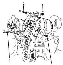
Loosen belt tightening nut (1) and bolt (2) and fulcrum bolt (3)
from failed alternator.
(4)
Remove belts and remove nut (1) and bolt (2) completely.
(5)
Remove fulcrum bolt (3) and nut (4) and lift alternator from engine.
(6)
Deleted
(7)
Remove four bolts (5) from alternator.
(8)
Separate slip ring end frame (6) and stator (7) from drive end frame
and rotor assembly (8).
Change 5 4-413
|