Order this information in Print

Order this information on CD-ROM

Download in PDF Format


Click here to make tpub.com your Home Page

Page Title: REPLACEMENT
Back | Up | Next

Click here for a printable version

Google


Web
www.tpub.com

Home


Information Categories
.... Administration
Advancement
Aerographer
Automotive
Aviation
Combat
Construction
Diving
Draftsman
Engineering
Electronics
Food and Cooking
Math
Medical
Music
Nuclear Fundamentals
Photography
Religion
USMC
   
Products
  Educational CD-ROM's
Printed Manuals
Downloadable Books


TM 5-4210-220-12 4-24 ELECTRICAL SYSTEM - Continued 4-24.  1 Alternator - Continued (9) 
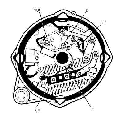
Remove nuts (9) and washers (10) and remove stator (7) from slip ring end frame (6). (10) Remove diode trio (11) by removing insulated screw (12). (11) Remove screw (13) and insulated washer (14). (12) Connect a 12 in. piece of # 16 white wire, with suitable ring terminal, to negative brush using screw (13) and washer (14).  Wire terminal must be under the insulated washer to ensure good electrical contact with brush terminal. (13) Remove  and  discard  the  black  regulator  jump  lead  (15)  between  the  voltage  regulator  and  the  positive (BAT) terminal of the alternator. 4-414

Privacy Statement - Press Release - Copyright Information. - Contact Us - Support Integrated Publishing

Integrated Publishing, Inc. - A (SDVOSB) Service Disabled Veteran Owned Small Business