|
| |
TM 5-4210-220-12
4-18. PUMP, PIPING, AND VALVES - Continued
(21) Lubricate O-ring (19) with silicone grease (28, Appendix E) and install into inner bore of tip
assembly (10).
(22)
Screw water tip (10) onto the turret head (11) and tighten firmly.
(23)
Lubricate O-ring (18) with silicone grease (item 27, Appendix E) and install into the outer bore groove on
the water tip (10).
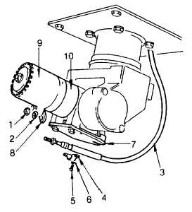
(24) Attach cable (3) to mounting plate (7) using conduit clamp (4) screws (5) and lockwashers (6) Do not
tighten screws (5).
(25) Carefully slide water sleeve (9) onto water tip (10) Make sure the cable (3) end rod protrudes through the
water sleeve link (8).
(26)
Install lockwasher (2) and nut (1) onto the cable (3) end rod and tighten firmly.
(27)
Set the control handle to 'FOG' position Ensure water sleeve (9) is fully retracted on the water tip (10).
(28)
Tighten conduit clamp screws (5) firmly.
(29)
Cycle control handle from 'FOG' to 'SOLID' a couple of times.
(30)
Set control handle to 'FOG' Cable adjustment is satisfactory if water sleeve (9) is seated against water tip
shoulder (10). If clearance is noticeable readjust by loosening screws (5) and repeating steps 27 thru 30.
4-281
|

