|
| |
TM 5-4210-220-12
4-18 PUMP, PIPING, AND VALVES - Continued
4-18.17 Bumper Turret - Continued
c. Nozzle Repair - Continued
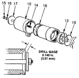
(6) Remove jam nut (15) and lockwasher (16)
that retains the button (17) to the button
shaft (14).
(7) If web (13) is damaged and needs to be
replaced, press it out of the tip assembly
(10) using an arbor press.
(8) Clamp the button shaft (14) in a vise and
remove jam nut (12).
(9) Unscrew web (13) from button shaft (14).
Discard web.
(10) Remove button shaft (14) from vise and
inspect for damage such as stripped
threads, corrosion or bends.
(11) Remove O-rings (18, 19) from tip
assembly (10). Discard O-rings.
NOTE
Small lime deposits can be dissolved by soaking parts in acetic acid (item 1, Appendix E) and
rubbing them with a brass bristle brush.
(12) Remove lime deposits, or corrosion using a brass bristle brush.
(13) Wipe all components using a soft, dry, lint-free cloth.
(14) Inspect all components for corrosion, cracks, or stripped or worn threads.
(15) Evidence of damage of any kind is cause for rejection. Replace component or assembly as required.
(16) If web was removed, press new web (13) into the tip (10) through the inlet end. Ensure the machined
face of the web is installed first.
(17) Attach button (17) to the button shaft (14), using lockwasher (16) and jam nut (15). Tighten jam nut to 9
ft lb (12 Nm).
(18) Apply threadlock liquid (item 29, Appendix E) to the button shaft (14) following manufacturer's
recommendations.
(19) Screw button shaft (14) into web until clearance between button (17) and tip assembly (10) is 0.14 in.
(3.6 mm) as shown.
(20) Install jam nut (12) onto button shaft (14) and tighten to 17 ft lb (23 Nm).
4-280
|