|
| |
TM 5-4210-220-12
4-18. PUMP, PIPING, AND VALVES-Continued
(5)
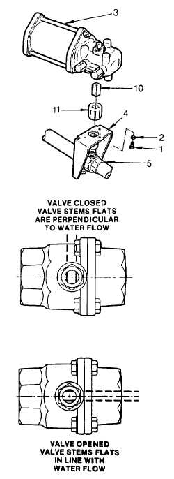
If the actuator has to be separated from valve to allow
removal of valve, remove the three capscrews (1) and
lockwashers (2) that retain the actuator (3) to the bracket (4).
(6)
Separate the actuator (3) from the bracket (4). Remove the
reducer (10) and coupling (11) and retain for installation.
(7)
Mark the position of the ball valve prior to removal.
(8)
Using two pipe wrenches, unscrew the ball valve (5) from the
piping system.
(9)
Inspect the foam piping and ball valves for stripped or
corroded threads. Replace defective parts.
(10)
Repair air actuator following procedures outlined in para. 4-
18.12.
INSTALLATION
(1)
Apply pipe sealant (item 22, Appendix E) to the threads and
install the ball valve onto one pipe end. Be sure the valve is
positioned the same as noted in REMOVAL preceding.
(2)
Install the second pipe into the ball valve. Be sure the piping
is in the same position as prior to removal.
NOTE
Actuator should be remounted on the ball valve
from which it was removed. Adjust actuator stops
each time valve is remounted.
(3)
Before installing actuator, it is necessary to know the open
and closed position of the valve.
(4)
Install the coupling onto the valve stem. It will be necessary to apply a small piece of electrical tape
(item 11, Appendix E) to obtain a tight fit between the valve stem and coupling. This will hold the
coupling in place while adjustments are made.
4-245
|

